Large-span heavy gantry numerical control machine tool
A CNC machine tool and large-span technology, which is applied in the field of CNC machine tools, can solve the problems of difficult processing of convex lines on the upper surface of the unloading beam, reduce machine tool vibration, and complex unloading structure, achieve excellent vibration damping performance, and improve processing. Good results for accuracy, size and thermal stability
- Summary
- Abstract
- Description
- Claims
- Application Information
AI Technical Summary
Problems solved by technology
Method used
Image
Examples
Embodiment 1
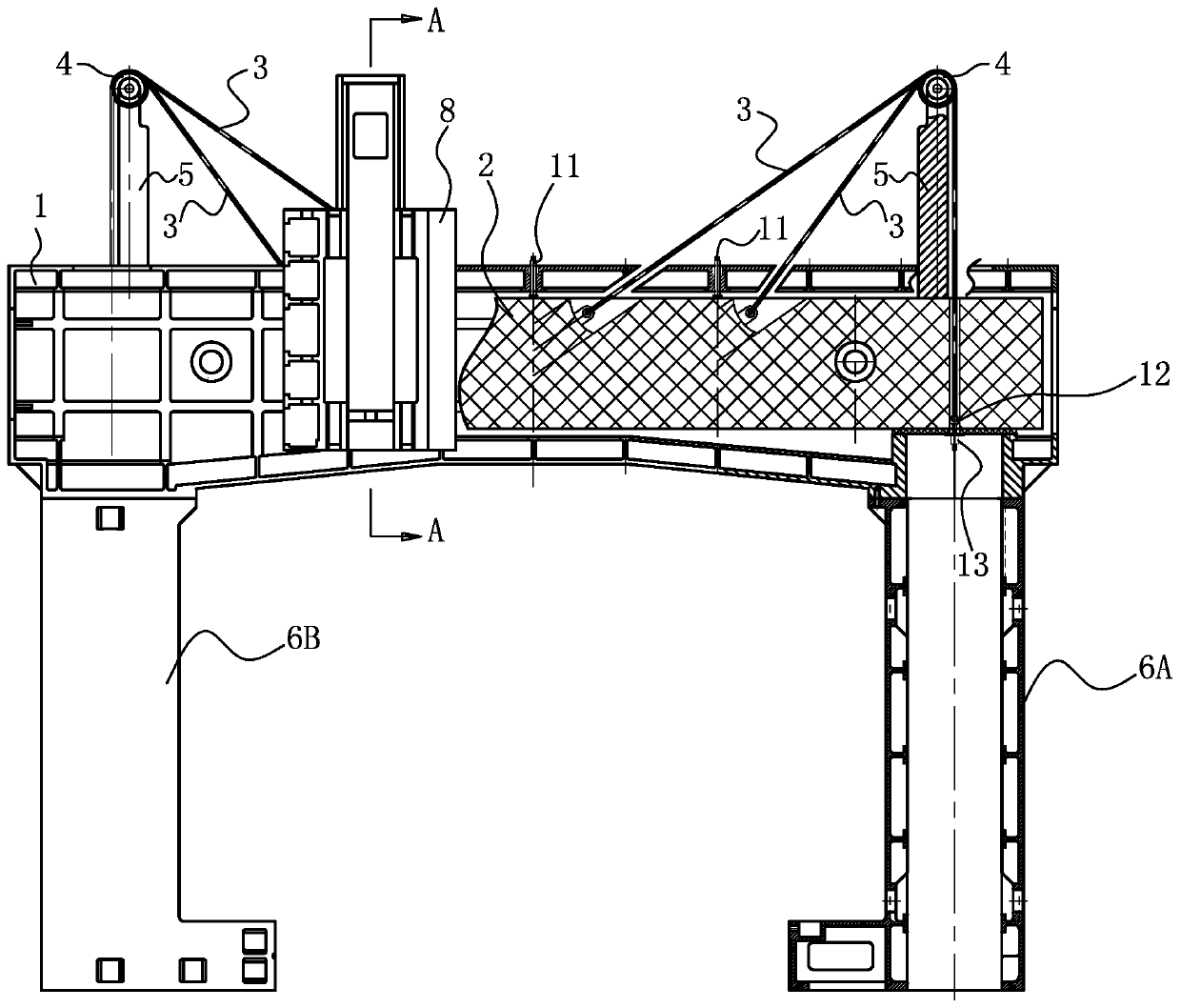
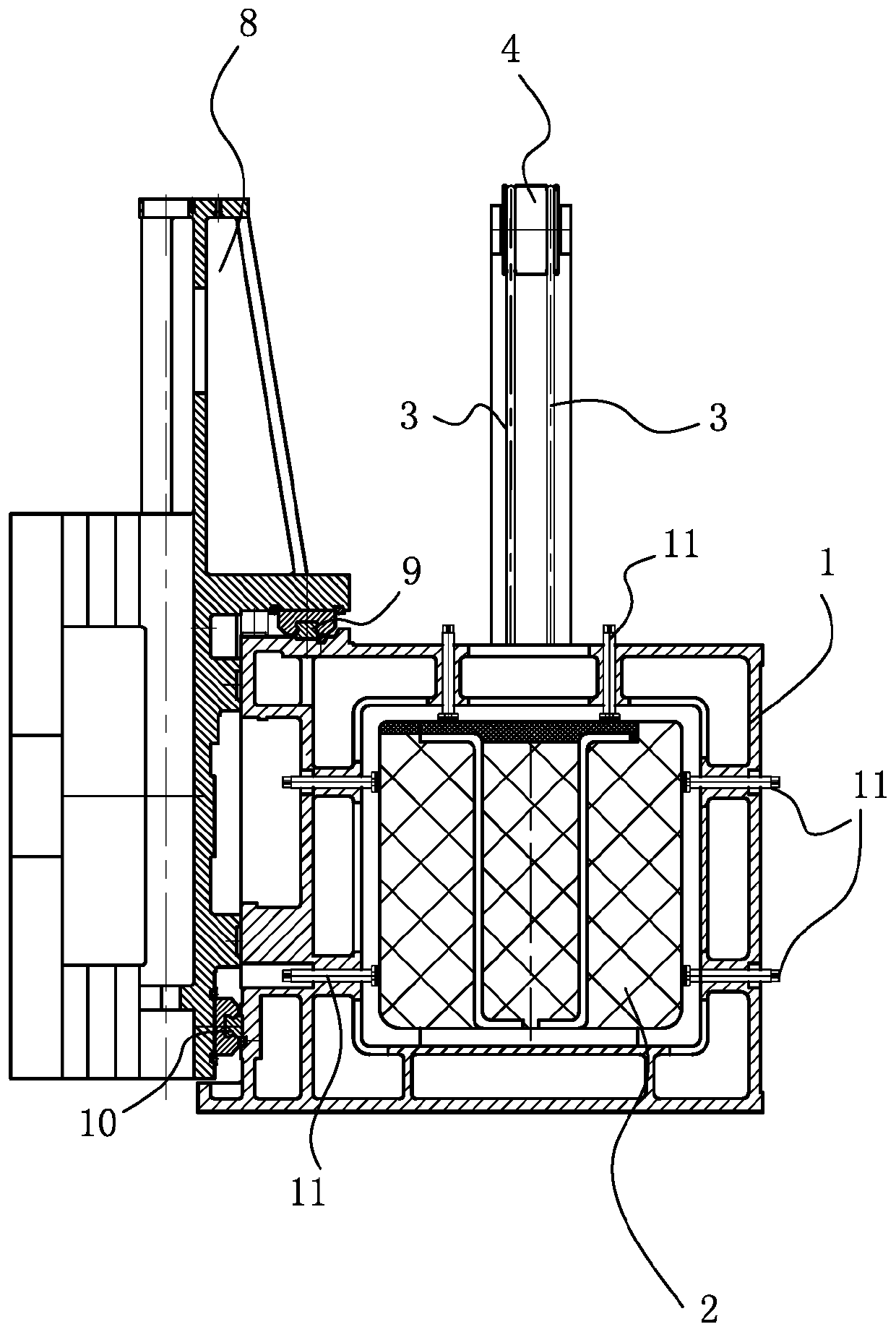
[0022] Such as figure 1 and figure 2 As shown, the machine tool is a large-span heavy-duty gantry CNC machine tool with a mobile gantry frame. The gantry frame includes a beam 1 and columns 6A and 6B fixedly connected to the two ends of the beam 1. The beam 1 is provided with guide rails. Small friction between the traversing slide 8 and the beam 1, the top guide rail 9 is set on the top of the beam 1, the side guide rail 10 is set on the side of the beam 1, and the traversing slide 8 is respectively provided with a top guide and a side guide The top guide part is slidably matched with the top guide rail, and the side guide part is slidably matched with the side guide rail 10.
[0023] The crossbeam 1 is a crossbeam with a hollow structure, and an unloading beam 2 of polymer concrete material is arranged in the hollow cavity of the crossbeam 1. The two ends of the unloading beam 2 are fixed in the hollow cavity at the end of the crossbeam 1. Adjusting screws 11 are respecti...
Embodiment 2
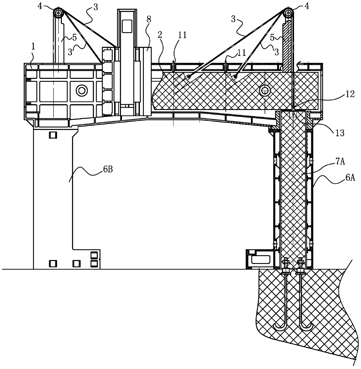
[0027] Such as image 3 As shown, Embodiment 2 is a large-span heavy-duty gantry CNC machine tool with a fixed gantry frame and a movable workbench. Its structure is basically the same as that of Embodiment 1. The difference is that the columns 6A and 6B are columns of hollow structure, and the columns The hollow cavities of 6A and 6B are respectively provided with supporting core columns 7A made of polymer concrete (the supporting core columns in column 6B are not shown), and the columns 6A, 6B and the supporting core columns are respectively fixed to the foundation. Since the supporting core column is provided, the two ends of the unloading beam 2 are respectively fixed on the top of a supporting core column, so that the vibration generated by the equipment can be absorbed more and faster.
PUM
 Abstract
Description
Claims
Application Information
 - R&D
- Intellectual Property
- Life Sciences
- Materials
- Tech Scout
- Unparalleled Data Quality
- Higher Quality Content
- 60% Fewer Hallucinations
Browse by: Latest US Patents, China's latest patents, Technical Efficacy Thesaurus, Application Domain, Technology Topic, Popular Technical Reports.
© 2025 PatSnap. All rights reserved.Legal|Privacy policy|Modern Slavery Act Transparency Statement|Sitemap|About US| Contact US: help@patsnap.com


