
Stone cutter

A cutting machine, stone technology, applied in the direction of stone processing tools, stone processing equipment, work accessories, etc., can solve the problems of motor stagnation, scratched work surface, uneven work surface, etc., to reduce friction and reduce scratches , Improve the effect of straightness and verticality

Active Publication Date: 2015-01-14
NANJING CHERVON IND
View PDF9 Cites 25 Cited by
  • Summary
  • Abstract
  • Description
  • Claims
  • Application Information

AI Technical Summary

Problems solved by technology

[0003] There are multiple defects in the above-mentioned existing stone cutting machine: firstly, the operator pushes the piece to be cut by hand to cut, and it is difficult to control the piece to be cut so that it can be fed straight along one direction. The cutting surface is not straight, it is difficult to ensure the straightness of cutting, which affects the cutting quality; secondly, when performing inclined cutting, the operator keeps the workpiece to be cut in the inclined position by hand on the one hand, and pushes the workpiece to be cut into the Yes, this method of completely relying on both hands to control the piece to be cut is difficult to keep the piece to be cut at the desired position, which is likely to cause unstable cutting and low cutting quality; in addition, the piece to be cut cannot be well controlled The resulting skew will cause the load of the motor to increase and stagnation occurs; moreover, the workpiece to be cut slides on the worktable, and the friction between the workpiece to be cut and the workbench will scratch the worktable, resulting in uneven worktable , so that the piece to be cut placed on the workbench is in a non-horizontal position, that is, it is not perpendicular to the blade, so that the cutting surface is a non-vertical surface

Method used


Image

  • Stone cutter
  • Stone cutter
  • Stone cutter

Examples


Embodiment Construction

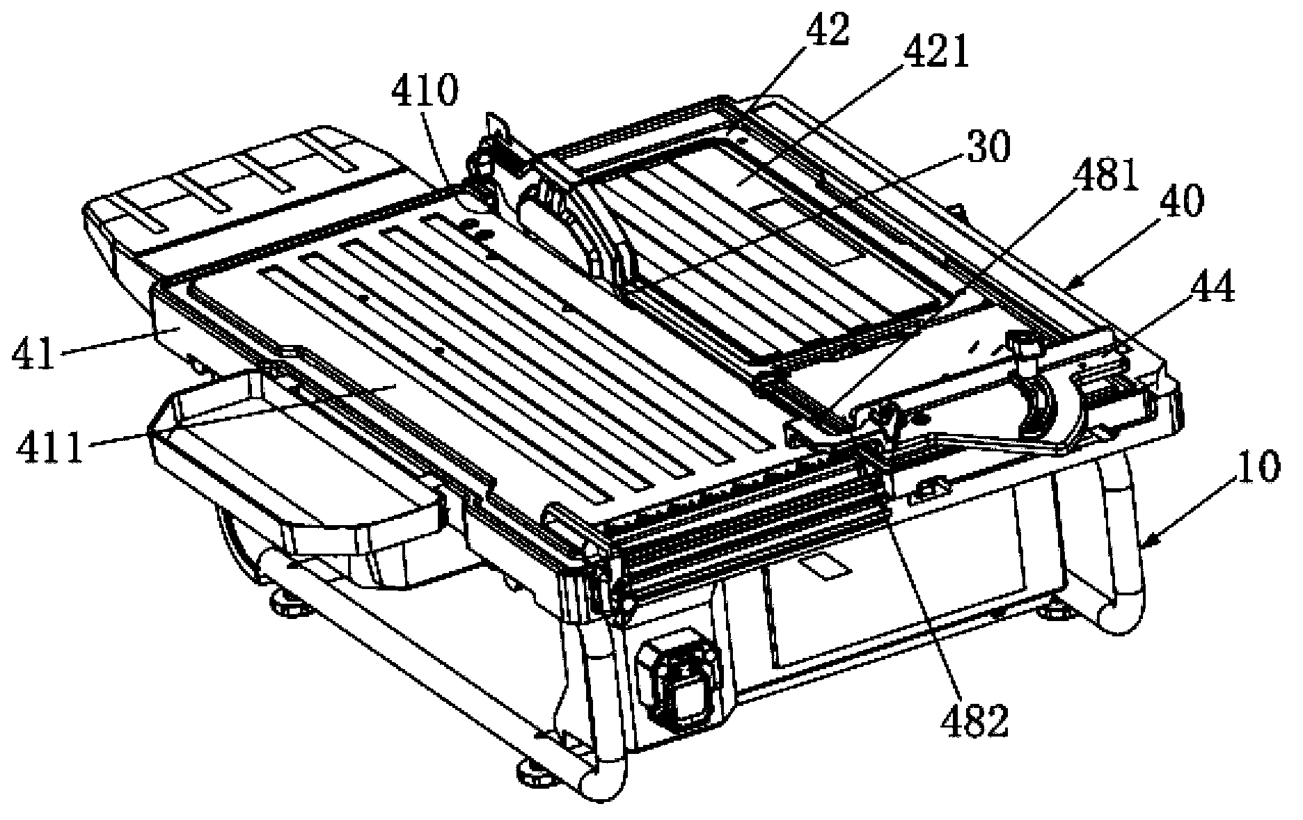
[0017] Such as figure 1 As shown, the stone cutting machine of the present invention comprises a base 10, a motor 20 accommodated in the base 10 (in figure 2 shown in ), the blade 30 driven by the motor 20 , and the workbench 40 supported on the base 10 .

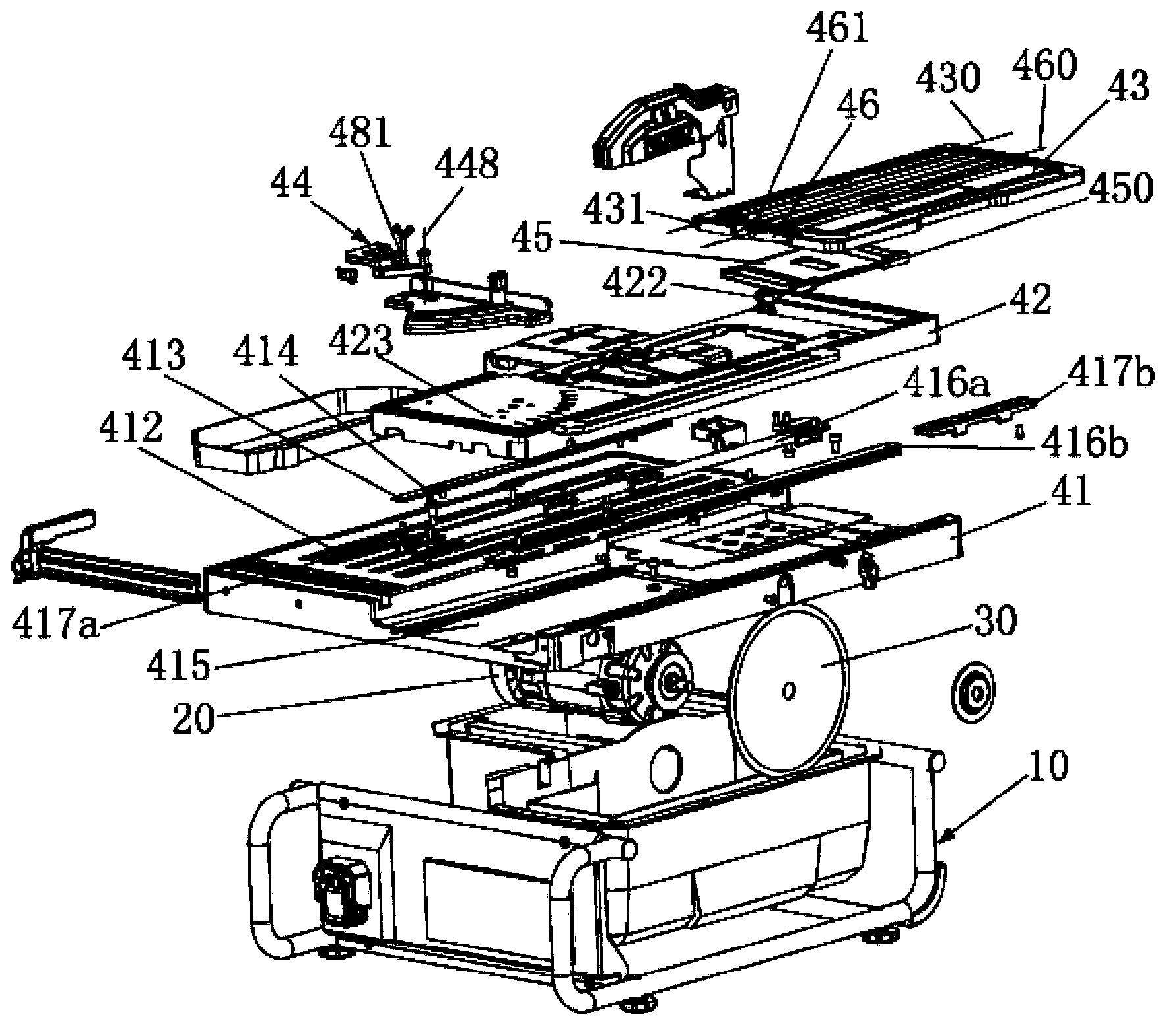
[0018] Such as figure 2 As shown, the workbench 40 includes a fixed workbench 41 and a movable workbench 42 .

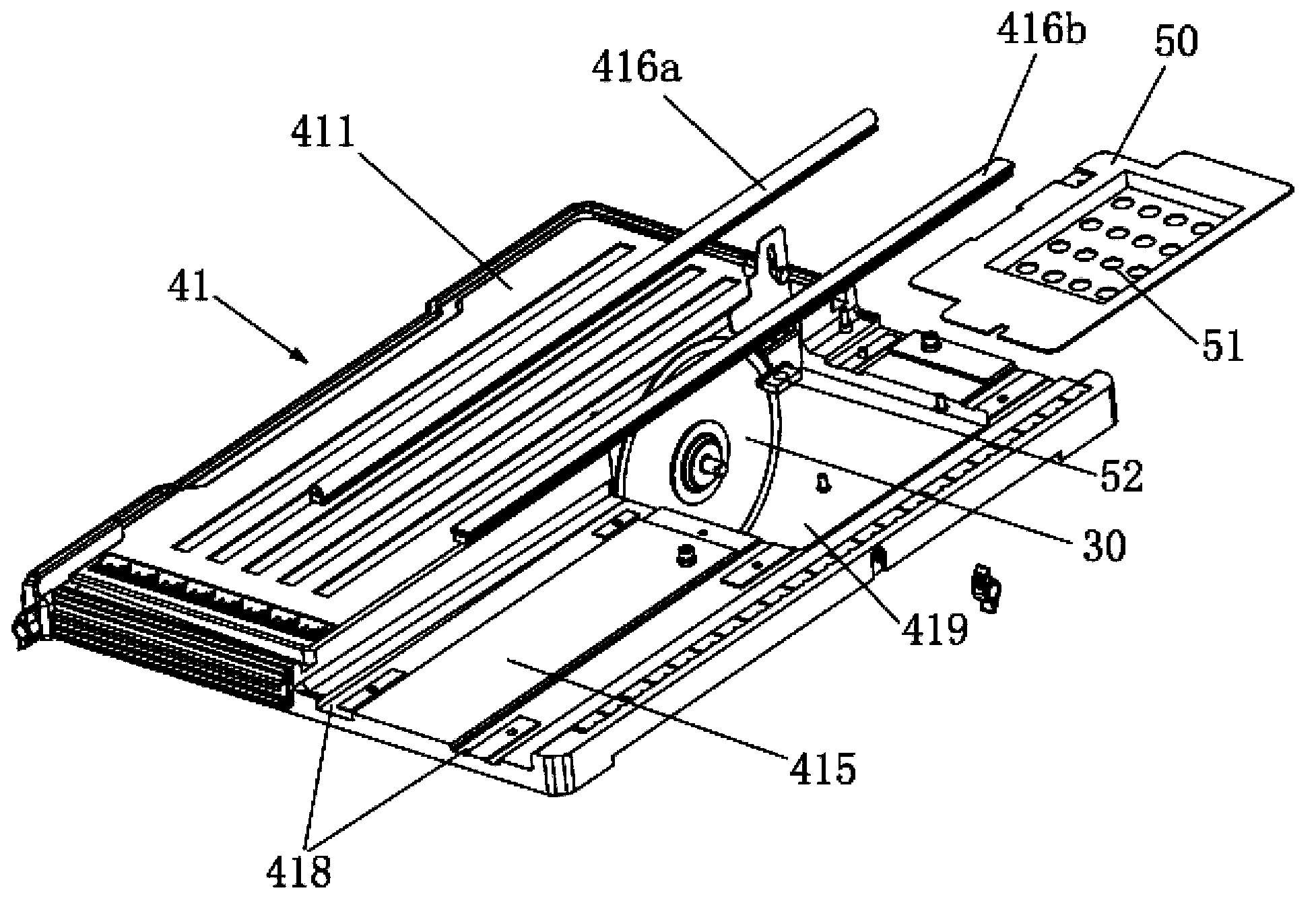
[0019] The fixed workbench 41 covers the entire base 10 . An elongated hole 410 is opened in the middle of the fixed workbench 41 , and the blade 30 protrudes from the elongated hole 410 and is partially located above the fixed workbench 41 . The fixed table 41 forms a first support surface 411 on the upper surface of one side of the blade 30 for supporting the piece to be cut (not shown). A plurality of grooves 412 for accommodating the adjusting pieces 413 are formed on the first supporting surface 411 , and the grooves 412 extend along a direction parallel to the plane of the blade 30 and are parallel to ...


PUM


Abstract

A tile cutting machine comprises a base, a motor accommodated in the base, a blade driven to rotate by the motor, and a working table supported on the base, wherein the working table comprises a fixed working table fixedly mounted to the base. A movable working table is slidably mounted to the fixed working table in a sliding direction parallel to a plane of the blade. The movable working table comprises a pivoting plate pivotally mounted to the movable working table about a pivoting axis parallel to the plane where the blade is located and a fence assembly mounted to the movable working table. The tile cutting machine can effectively enhance the ability to produce straight and / or square cuts.

Description

technical field [0001] The invention relates to a stone cutting machine, in particular to a working table of the stone cutting machine. Background technique [0002] Stone cutting machines are widely used for cutting stone materials such as ceramic tiles and ceramic tiles. Existing stone cutting machines usually include a base, a motor inside the base, a blade driven by the motor, and a workbench supported on the base. There is an elongated hole in the middle of the workbench, and the blade protrudes from the elongate hole and is partially positioned above the workbench. During operation, the piece to be cut is placed on the workbench, and the operator slowly pushes the piece to be cut toward the rotating blade to perform cutting. [0003] There are multiple defects in the above-mentioned existing stone cutting machine: firstly, the operator pushes the piece to be cut by hand to cut, and it is difficult to control the piece to be cut so that it can be fed straight along o...

Claims


Application Information

Patent Timeline
Patent Type & Authority Applications(China)
IPC IPC(8): B28D1/24B28D7/04
CPCB28D7/043B28D1/24B28D1/047B28D1/228
Inventor 陈智丰
Owner NANJING CHERVON IND
Learn More