Method for filling gaps between steel plates

A filling method and steel plate technology, applied in the direction of welding medium, arc welding equipment, welding/cutting medium/material, etc., to achieve the effect of increasing strength, improving toughness, and reducing cold crack sensitivity

Active Publication Date: 2020-01-24
浙江高圣钢结构有限公司
View PDF5 Cites 2 Cited by
  • Summary
  • Abstract
  • Description
  • Claims
  • Application Information

AI Technical Summary

Problems solved by technology

However, for gap filling between high-strength steel plates, the fatigue strength will not improve as long as the conventional gap filling technology between steel plates is used

Method used


Image

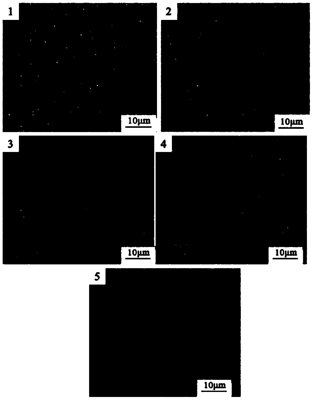
  • Method for filling gaps between steel plates
  • Method for filling gaps between steel plates
  • Method for filling gaps between steel plates

Examples


Embodiment 1

[0046] A method for filling gaps between steel plates, comprising the following steps:

[0047] S1: Clean the gap between the steel plates to be filled. The steel plates are low-alloy high-strength steels. The composition is shown in Table 1, and the mechanical properties are shown in Table 2;

[0048] S2: Preheating the gap filling area at 70 °C;

[0049] S3: Use welding filler to weld and fill the gaps between the steel plates to form joints, and perform three-layer welding on the joints, each layer is welded three times, and the weld seam must be ground before the next layer is welded;

[0050] In this embodiment, the welding adopts semi-automatic mixed gas shielded welding, and the welding shielding gases are He, Ar and CO 2 Mixed gas shielding, He, Ar and CO 2 The volume ratio is 1:1.2:0.15, and the polarity of the power supply is reversed; the welding seam forming method is single-sided welding, double-sided forming, and the welding process parameters are shown in Tabl...

Embodiment 2

[0059] A method for filling gaps between steel plates, comprising the following steps:

[0060] S1: Clean the gap between the steel plates to be filled, the steel plate is the low-alloy high-strength steel used in Example 1;

[0061] S2: Preheating the gap filling area at 85 °C;

[0062] S3: Use welding filler to weld and fill the gap between the steel plates to form a joint, and perform 4-layer welding on the joint, with 4 welds for each layer, and the weld seam must be ground before the next welding;

[0063] In this embodiment, the welding adopts semi-automatic mixed gas shielded welding, and the welding shielding gases are He, Ar and CO 2 Mixed gas shielding, He, Ar and CO 2 The volume ratio is 1:1.2:0.15, and the polarity of the power supply is reversed; the welding seam forming method is single-sided welding, double-sided forming, and the welding process parameters are shown in Table 4.

[0064] The welding filler used in this embodiment includes 30% by weight of iron...


PUM

PropertyMeasurementUnit
yield strengthaaaaaaaaaa

Abstract

The invention provides a method for filling gaps between steel plates, and belongs to the technical field of metal materials. The method comprises the following steps: cleaning to-be-filled gaps between steel plates; preheating the gap filling area under 150-250 DEG C; and welding and filling the gaps between the steel plates to form joints by using welding filler, wherein the joint strength matching is equal strength matching, and the welding filler comprises, by weight percent, 26-33% of iron, 12-15% of chromium, 0.15-0.18% of carbon, 0.05-0.1% of selenium, 2.1-2.7% of manganese, 0.8-1.2% ofsilicon and 0.1-0.5% of yttrium. The filling method provided by the invention not only enables the strength of the obtained joints to reach more than 98.3% of the strength of the steel plates, but also enables the structure of a welding seam of the joints to be mainly made of acicular ferrite with better strength and toughness, improves the toughness of the joints and improves the filling qualityof the gaps between the steel plates.

Description

technical field [0001] The invention belongs to the technical field of metal materials, and in particular relates to a method for filling gaps between steel plates. Background technique [0002] With the continuous innovation of steel structure production technology and the rapid development of the construction industry, steel structures are widely used in housing construction, bridges and some large-span engineering projects due to their high strength, good toughness, and good seismic performance. And the use has played a significant effect, so it has won the strong support of the country, making my country a big country in the production and processing of steel structures, and the steel structure industry has also entered a stage of vigorous development. In the process of continuous research and development of steel structures, new steel materials and their production and processing technologies are constantly innovating. With the rapid development of urbanization, a large...

Claims


Application Information

Patent Timeline
Patent Type & Authority Applications(China)
IPC IPC(8): B23K9/16B23K35/30
CPCB23K9/16B23K35/308
Inventor 陈晓平盛长华
Owner 浙江高圣钢结构有限公司
Why Eureka
Try Eureka