
Method for padding of split bolt hole of concrete shear wall

A technology of concrete shear wall and tie bolt holes, which is applied to building components, building insulation materials, etc., can solve the problems of unsatisfactory filling effect, unable to fill at one time, unable to guarantee full hole filling, etc., and achieve good anti-seepage and heat preservation effect. , Improve the effect of filling quality

Inactive Publication Date: 2014-01-29
BAOJI NO 1 CONSTR
View PDF7 Cites 7 Cited by
  • Summary
  • Abstract
  • Description
  • Claims
  • Application Information

AI Technical Summary

Problems solved by technology

The traditional pull bolt holes cannot be filled at one time, and the filling needs to be filled in multiple times, not only on the inner side, but also on the outer side.
When the outside is blocked, the outer frame needs to be used, which is very inconvenient and unsafe for construction
The traditional way of filling bolt holes is to fill while inserting and pounding at the same time. For this filling method, due to the responsibility of the operator, it is likely to cause both ends to be filled and the middle to be empty. It cannot guarantee the filling of the entire hole, making the filling impossible. Dense, the filling effect is relatively low, and the filling effect is not ideal, which will eventually lead to leakage of the outer wall, poor insulation effect, and a cold bridge will be formed at this part

Method used


Image

  • Method for padding of split bolt hole of concrete shear wall
  • Method for padding of split bolt hole of concrete shear wall
  • Method for padding of split bolt hole of concrete shear wall

Examples


Embodiment Construction

[0020] In order to make the object, technical solution and advantages of the present invention clearer, the present invention will be further described in detail below in conjunction with the accompanying drawings and embodiments. It should be understood that the specific embodiments described here are only used to explain the present invention, not to limit the present invention.

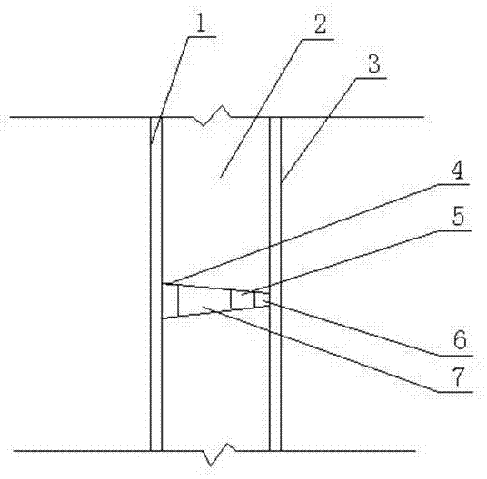
[0021] A kind of filling method of concrete shear wall tension bolt hole, such as figure 1 As shown, the steps are:

[0022] 1) Form the tension bolt holes in the concrete shear wall: After the shear wall reinforcement is bound, install the shear wall formwork, place the variable cross-section tension bolt casing and the tension bolt rod, and tighten the formwork through the tension bolt tightening device For reinforcement, after the formwork is strengthened, pour the shear wall concrete. After the concrete solidifies and does not stick to the mold, loosen the tension bolts, remove the tension bol...


PUM

PropertyMeasurementUnit
Lengthaaaaaaaaaa
Diameteraaaaaaaaaa
Wall thicknessaaaaaaaaaa

Abstract

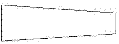
The invention discloses a method for padding of a split bolt hole of a concrete shear wall. According to the method for padding of the split bolt hole of the concrete shear wall, a traditional uniform-section split bolt is replaced by a variable-section split bolt sleeve when a shear wall formwork is reinforced. The method for padding of the split bolt hole of the concrete shear wall comprises the following steps that the split bolt hole is formed in the concrete shear wall, a variable-section circular truncated cone rubber plug is placed and stuffed in the split bolt hole from the inner side of the concrete shear wall, a polyurethane foaming material which has the air hardening performance, resists seepage and preserves heat is injected into the split bolt hole, and an inner portion with the length of 15mm of the split bolt hole and an outer portion with the length of 15mm of the split bolt hole are reserved and padded with expanded mortar. According to the method for padding of the split bolt hole of the concrete shear wall, full-hole padding is guaranteed and padding is dense; the polyurethane foaming material which has the air hardening performance, resists seepage and preserves heat is used for padding, so that the padding quality is improved, and the seepage-proof and heat-preservation effect is good.

Description

technical field [0001] The invention is used in the construction industry, and in particular relates to a filling method for tension bolt holes in concrete shear walls. Background technique [0002] The tension bolt hole of the concrete shear wall is a hole that must be set when the concrete shear wall formwork is reinforced. For the filling of the tension bolt hole of the concrete shear wall, expansion expansion mortar is usually used for filling. The traditional split bolt holes cannot be filled at one time, and the filling needs to be filled in multiple times, not only on the inner side, but also on the outer side. When the outside is blocked, the outer frame needs to be used, and the construction is very inconvenient and unsafe. The traditional way of filling bolt holes is to fill one side and insert and tamp at the same time. For this filling method, due to the responsibility of the operator, it is likely to cause both ends to be filled and the middle to be empty. It c...

Claims


Application Information

Patent Timeline
IPC IPC(8): E04B1/66
Inventor 程志强庄波韩博
Owner BAOJI NO 1 CONSTR
Learn More