Electrolytic rhodium plating solution
A technique for electroplating solution and electrolysis of rhodium, which is applied in the field of electrolytic rhodium electroplating solution and can solve problems such as peeling off of substrates, cracks, etc.
- Summary
- Abstract
- Description
- Claims
- Application Information
AI Technical Summary
Problems solved by technology
Method used
Image
Examples
Embodiment 1
[0064] Use rhodium (as rhodium sulfate) concentration and phosphorus concentration (as sodium phosphite) to be the electrolytic rhodium electroplating solution (sulfuric acid 40mL / L, pH=0.6, bath temperature 60 ℃) of the number 01~06 in the left column of Table 1, in 20mm×20mm copper test piece, with 4A / dm 2 Electroplate at a current density to a thickness of 0.10 μm.
[0065] The appearances of the obtained rhodium-phosphorus electroplating test pieces were all in a silver-white amorphous state. With the rhodium-phosphorus electroplating test piece as the anode and the copper test piece of 40mm × 20mm as the cathode, apply a low voltage of 0.74V, measure the porosity in 5% sulfuric acid solution for 20 minutes, and obtain the results in the right column of Table 1. In addition, the porosity when a test piece not subjected to rhodium-phosphorus plating was used as an anode was defined as 100%.
[0066] [Table 1]
[0067]
[0068] From these results, it can be seen that i...
Embodiment 2
[0073] Then, use the electrolytic rhodium electroplating solution (pH =0.6, bath temperature 60°C), for a 20mm×20mm copper test piece, 4A / dm 2 current density, electroplating to a thickness of 0.10 μm.
[0074] [Table 2]
[0075]
[0076] From these results, it can be seen that when the concentration of rhodium (rhodium phosphate) is 4.0 g / L, the porosity becomes extremely low when the ratio of phosphorus concentration (potassium phosphite) to rhodium metal is 1 / 100 or more. In addition, when the phosphorus concentration was increased to 9.5 g / L, the porosity was 10% or less.
Embodiment 3
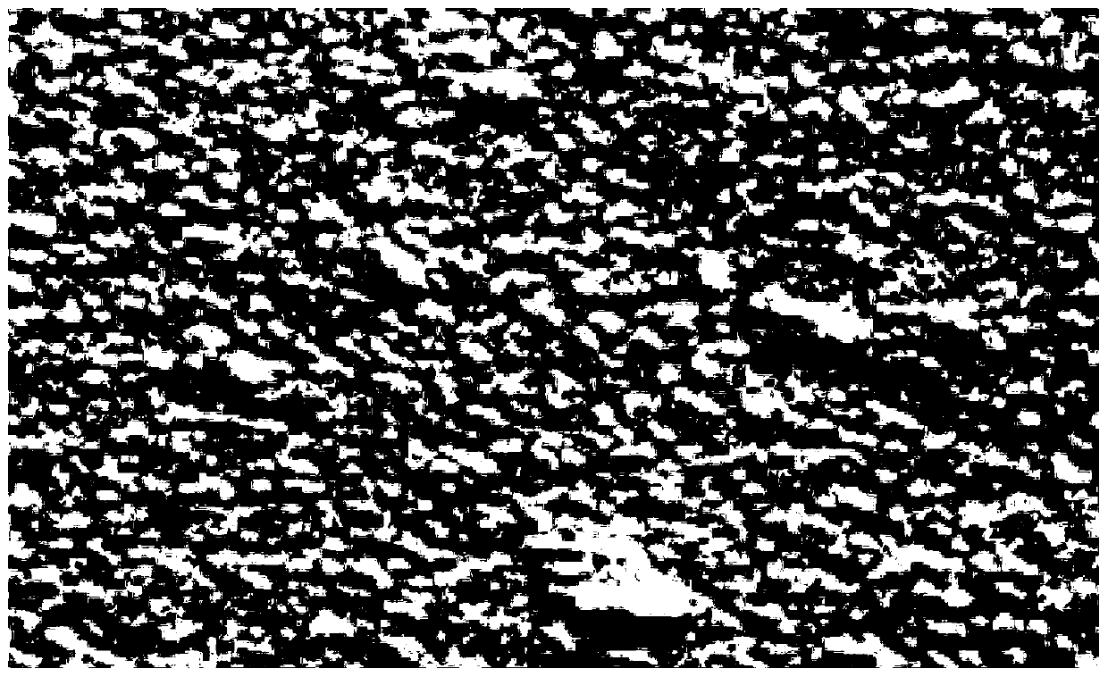
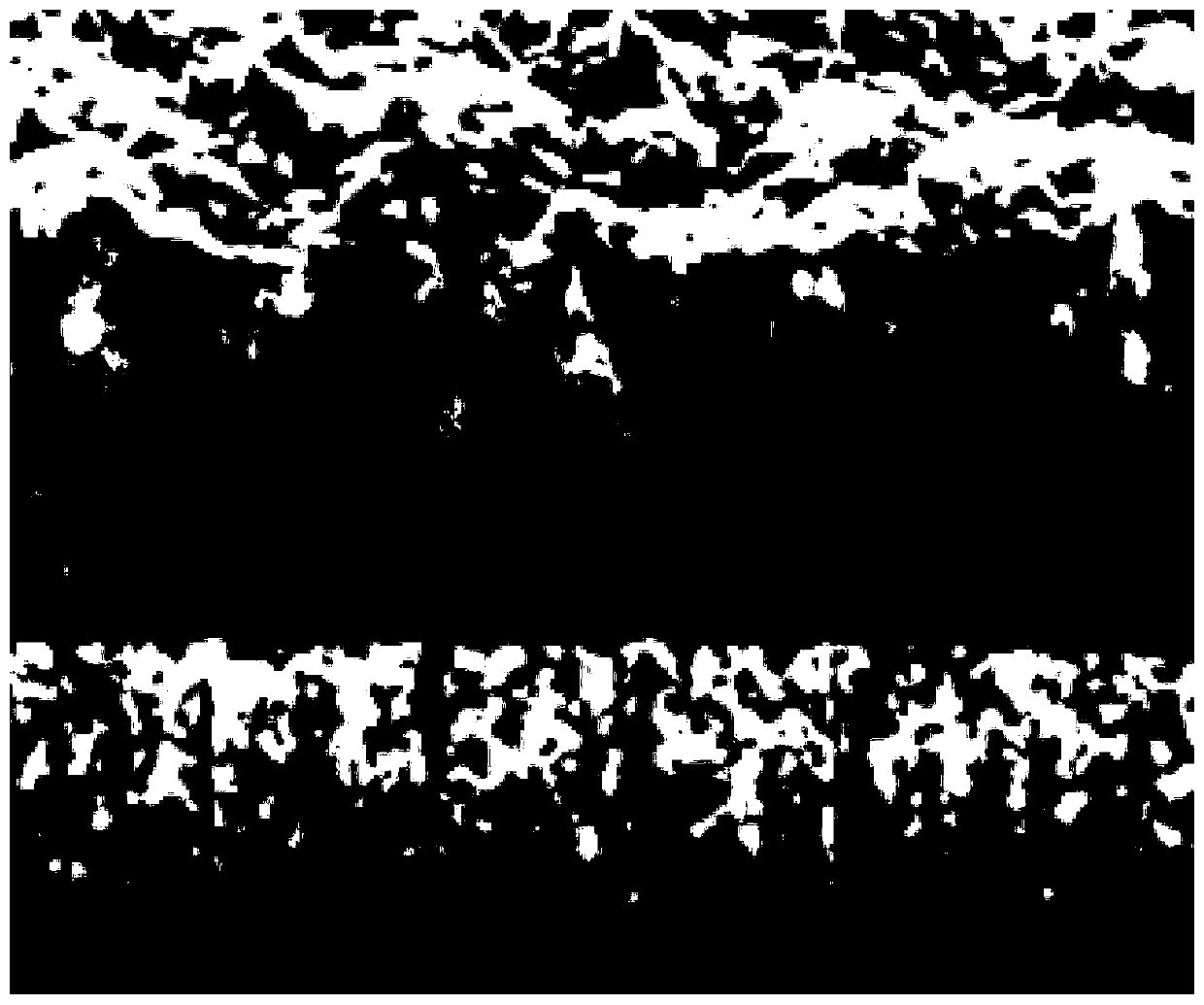
[0080] Use the electrolytic nickel plating solution of nickel sulfate 200g / L, sodium chloride salt 15g / L and phosphoric acid 0.15mL / L to electroplate 8μm on a 20mm×20mm copper test piece. Gold strike plating was performed on the surface of the nickel film, and its scanning electron microscope image (30,000 times) was displayed on figure 1 . It can be seen that the surface morphology of the nickel film emphatically contrasted by the gold strike plating forms an undulating pattern.
[0081] Afterwards, on the nickel film, a rhodium-phosphorus strike bath (strike bath) of 1 g / L with rhodium (as rhodium sulfate) and a phosphorus concentration (as calcium phosphite) of 1 g / L was used to implement 10V×10 seconds. After rhodium phosphorus impact plating, rhodium (as rhodium sulfate) concentration is 4.0g / L, sulfuric acid is 50mL / L, with 4A / dm 2 The current density is high, and the pure rhodium film is electroplated to a thickness of 0.5 μm.
[0082] Then, for the test piece of el...
PUM
| Property | Measurement | Unit |
|---|---|---|
| Vickers hardness | aaaaa | aaaaa |
| thickness | aaaaa | aaaaa |
| thickness | aaaaa | aaaaa |
Abstract
Description
Claims
Application Information
 - R&D
- Intellectual Property
- Life Sciences
- Materials
- Tech Scout
- Unparalleled Data Quality
- Higher Quality Content
- 60% Fewer Hallucinations
Browse by: Latest US Patents, China's latest patents, Technical Efficacy Thesaurus, Application Domain, Technology Topic, Popular Technical Reports.
© 2025 PatSnap. All rights reserved.Legal|Privacy policy|Modern Slavery Act Transparency Statement|Sitemap|About US| Contact US: help@patsnap.com


