
Method for preparing friction-reducing and wear-resistant porous coating on inner surface of shaft sleeve type part

A porous coating and inner surface technology, applied in the coating, metal material coating process, etc., can solve the problems of large residual stress, weakened coating performance, poor coating forming, etc., to achieve easy industrial production and wide applicability , the effect of high utilization rate

Active Publication Date: 2019-11-22
NANJING INST OF TECH
View PDF3 Cites 3 Cited by
  • Summary
  • Abstract
  • Description
  • Claims
  • Application Information

AI Technical Summary

Problems solved by technology

However, the heat sources of ion spraying, laser cladding, arc spraying, and surfacing welding have high operating temperatures, and it is difficult to find suitable pore-forming agents to prepare porous coatings with controllable porosity and connected pores.
[0005] Second, the above-mentioned coating methods belong to non-equilibrium thermal processing. The residual stress of the coating itself and the coating / part interface is large, which can easily lead to cracking or peeling off of the coating. The non-equilibrium heat balance process even leads to deformation of the part
In addition, due to the large amount of heat input to the base material by methods such as laser cladding and surfacing welding, when the coating is prepared on the inner surface of non-ferrous metal shaft sleeve parts, a large amount of base material melts into the coating, forming a large Coating dilution rate, which weakens the coating performance and leads to poor coating formation

Method used


Image

  • Method for preparing friction-reducing and wear-resistant porous coating on inner surface of shaft sleeve type part
  • Method for preparing friction-reducing and wear-resistant porous coating on inner surface of shaft sleeve type part
  • Method for preparing friction-reducing and wear-resistant porous coating on inner surface of shaft sleeve type part

Examples


Embodiment 1

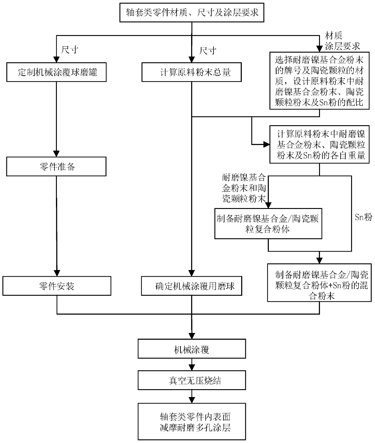
[0060] The material of the shaft sleeve parts is copper, the inner diameter is 100mm, the height is 100mm, the thickness is 10mm, and the inner surface area is 31400mm 2 , the coating hardness is required to be greater than HRC20, the porosity is 10-14%, and the coating thickness is 0.8-1.2mm.

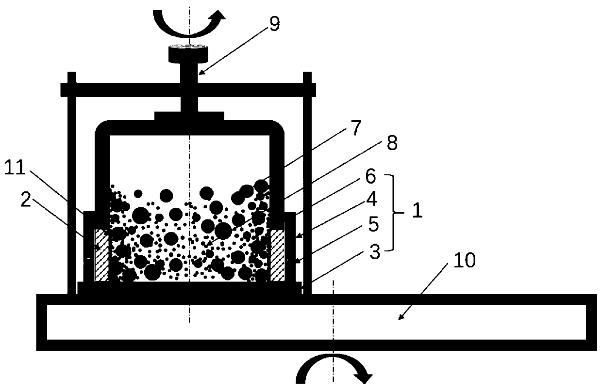
[0061] The structure of the ball mill is as follows figure 2 As shown, the height of the tank body is 220mm, the thickness of the rubber sealing gasket is 0.5mm, and the thickness of the rubber compression gasket is 5mm.

[0062] The total amount of raw material mixed powder is: 31400*0.010=314(g).

[0063] The grade of wear-resistant nickel-based alloy powder is selected as Ni25, and the mass percentage of Ni25 is composed of: C 0.1%, Cr 0, Fe≤8%, Si 3.5%, B 1.5%, Ni balance; the material of ceramic particle powder is WC.

[0064] The ratio of three components such as Ni25 powder, WC powder and Sn powder in the raw material mixed powder is: (Ni25 0.85 WC 0.15 ) 0.84 sn 0.16 , w...

Embodiment 2

[0073] The shaft sleeve parts are made of low carbon steel Q235, with an inner diameter of 100mm, a height of 100mm, a thickness of 10mm, and an inner surface area of ​​31400mm 2 , the coating hardness is required to be greater than HRC45, the porosity is 10-14%, and the coating thickness is 0.8-1.2mm.

[0074] Using the same parameters as in Example 1, the grade of wear-resistant nickel-based alloy powder is selected as Ni60, and the mass percentage of Ni60 is composed of: C 0.8%, Cr 16%, Fe≤15%, Si 4.5%, B 3.5%, Ni balance ; Select the material of the ceramic particle powder as WC.

[0075] The ratio of three components such as Ni60 powder, WC powder and Sn powder in the raw material mixed powder is: (Ni60 0.8 WC 0.2 ) 0.84 sn 0.16 , wherein, the particle size of Ni60 powder is less than 50 μm; the particle size of WC powder is less than 5 μm; the particle size of Sn powder is less than 20 μm, and the purity is greater than 99.5%.

[0076] The raw material mixed powder ...

Embodiment 3

[0079] The material of the shaft sleeve parts is copper, the inner diameter is 100mm, the height is 100mm, the thickness is 10mm, and the inner surface area is 31400mm 2 , the coating hardness is required to be greater than HRC20, the porosity is 18-25%, and the coating thickness is 0.8-1.2mm.

[0080] Using the same parameters as in Example 1, the grade of wear-resistant nickel-based alloy powder is selected as Ni25, and the mass percentage of Ni25 is composed of: C 0.1%, Cr 0%, Fe≤8, Si 3.5%, B 1.5%, Ni balance; Select the material of the ceramic particle powder as WC.

[0081] The ratio of three components such as Ni25 powder, WC powder and Sn powder in the raw material mixed powder is: (Ni25 0.85 WC 0.15 ) 0.73 sn 0.27 , wherein, the particle size of Ni25 powder is less than 50 μm; the particle size of WC powder is less than 5 μm; the particle size of Sn powder is less than 20 μm, and the purity is greater than 99.5%.

[0082] The raw material mixed powder contains 19...


PUM

PropertyMeasurementUnit
The inside diameter ofaaaaaaaaaa
Internal surface areaaaaaaaaaaa
Heightaaaaaaaaaa

Abstract

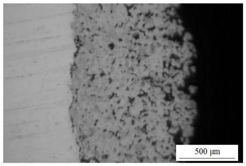
The invention discloses a method for preparing a friction-reducing and wear-resistant porous coating on the inner surface of a shaft sleeve type part. The method comprises the following steps of: polishing the inner surface of the part, washing and drying the part; installing the part in a mechanically coating ball-milling tank; putting a certain amount of mixed powder and several hard alloy grinding balls in a ball grinding tank, wherein the mixed powder comprises nickel-based alloy powder, ceramic particle powder and Sn powder; closing the ball-milling tank, and carrying out ball milling under the protection of an inert gas to achieve mechanical coating of the inner surface of the part; and putting the coated part in a vacuum furnace, and carrying out vacuum pressureless sintering to form the friction-reducing and wear-resistant porous coating with the thickness of 1.2mm and the porosity of 5 to 25%. The prepared coating is tightly bonded to the inner surface of the part, and has small residual stress, connected and uniformly distributed pores, and excellent mechanical properties and tribological properties under oil lubrication. The method is suitable for shaft sleeve type partsmade from various materials including non-ferrous metals, is simple in process and low in cost and has no environmental pollution.

Description

technical field [0001] The invention relates to a method for preparing a coating, in particular to a method for preparing a friction-reducing and wear-resistant porous coating on the inner surface of shaft sleeve parts, and belongs to the technical field of surface engineering. Background technique [0002] The inner surface of shaft sleeve parts is required to have good wear resistance. Coating a layer of wear-resistant coating on the inner surface of shaft sleeve parts is a common method to improve its wear resistance, such as coating nickel-based alloy layer, Al 2 o 3 Ceramic layer, hard alloy layer, etc., the coating methods currently used mainly include plasma spraying method, laser cladding method, arc spraying method, surfacing welding method, etc. [0003] There are two main problems in adopting these coatings and coating methods: [0004] First, in order to protect the shaft, in addition to ensuring good wear resistance of the inner surface of the shaft sleeve par...

Claims


Application Information

Patent Timeline
IPC IPC(8): C23C24/10C22C19/05C22C32/00
CPCC22C19/058C22C32/0005C22C32/001C22C32/0052C23C24/103
Inventor 杨宗辉沈以赴杨修荣王玉文徐振钦张栩琛肖叔贤
Owner NANJING INST OF TECH
Learn More