
Intraoral video camera and display system

a video camera and display system technology, applied in the field of intraoral video cameras and display systems, can solve the problems of not being able to prove the profitability of one-time treatment, not being able to secure the health of the oral cavity, and not being able to find the suitable means for dealing, etc., to achieve easy understanding, accurate display, and increase the effect of dental practice profits

Inactive Publication Date: 2013-10-31
ADVANCE CO LTD
View PDF7 Cites 191 Cited by
  • Summary
  • Abstract
  • Description
  • Claims
  • Application Information

AI Technical Summary

Benefits of technology

The present invention is a dental practice system that allows dental professionals to capture and display a clear panoramic image of a patient's teeth using the actual image and sometimes an X-ray image. The display shows the patient's teeth in a way that is easy to understand for explaining the diagnosis and treatment. The invention also accurately displays the position of an intraoral camera and allows the camera to be adjusted for viewing the captured image. Patients can use a portable display to check the situation in their oral cavity and the necessity of diagnosis and treatment. This system improves the possibility of on-going diagnosis and treatment and care for maintaining intraoral health, increasing the profits in the dental practice, and improving other business aspects. The invention also enables all processing in the dental practice to be handled using a mobile terminal able to process digital data and thereby reducing costs and improving efficiency.

Problems solved by technology

Further, with such one-time visits to the clinic, a healthy oral cavity is not secured.
For the business operations of a dental practice as well, one-time treatment sometimes cannot by any means be said to be good in terms of profitability, but there were no means found which were suitable for dealing with this.

Method used


Image

  • Intraoral video camera and display system
  • Intraoral video camera and display system
  • Intraoral video camera and display system

Examples


first embodiment

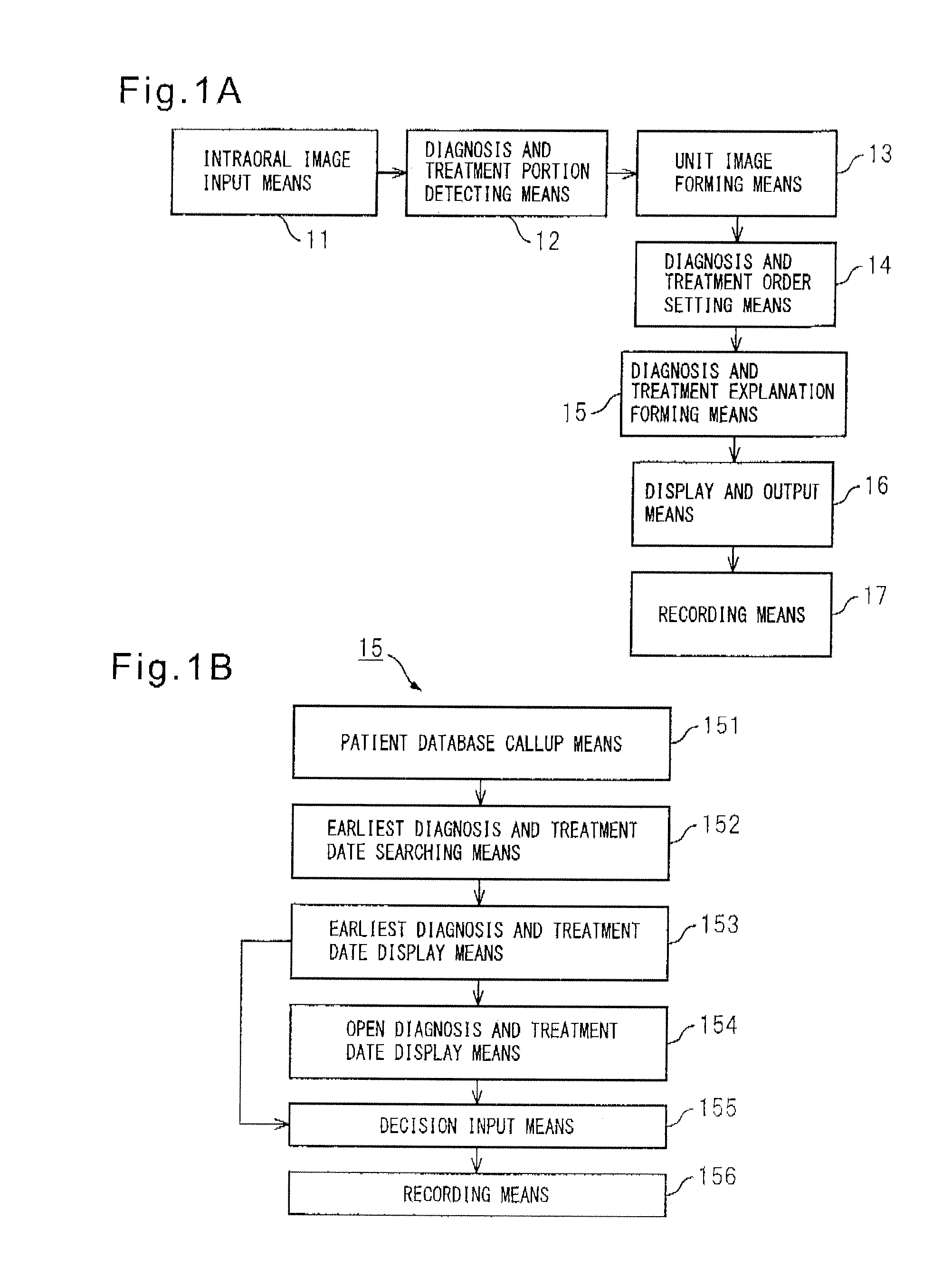
[0102]FIG. 1A is a view which, shows an embodiment of the present invention. In the figure, reference numeral 11 indicates an intraoral image inputting means, for example, a device which uses a camera for capturing images of all teeth of the upper jaw and lower jaw so as to obtain digital image data.

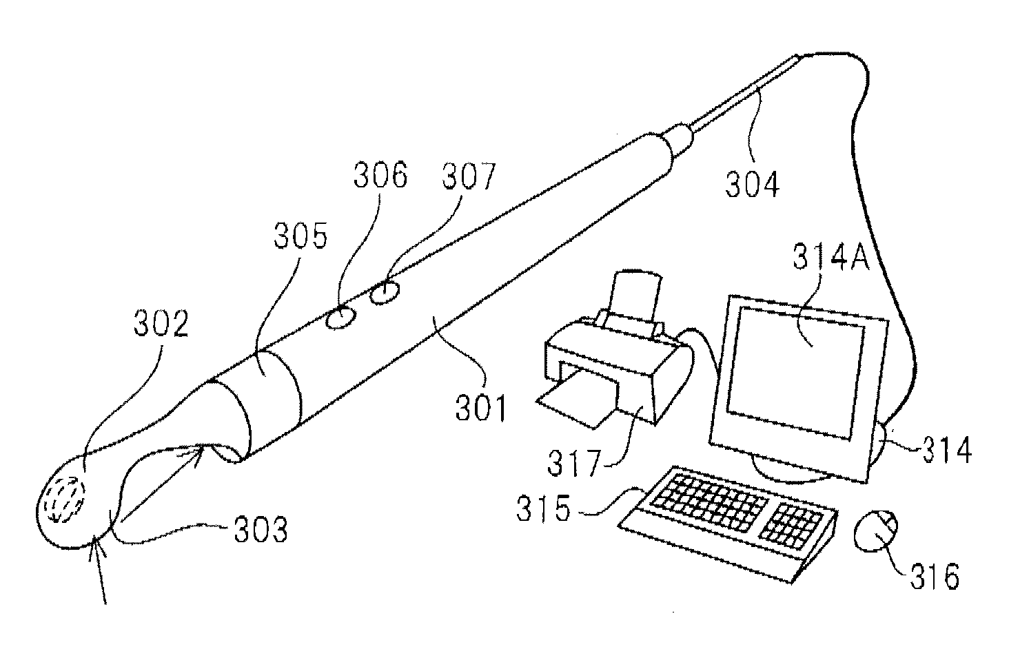
[0103]The intraoral image inputting means 11 is, for example, a reflection type of dental camera which uses a convex mirror such as shown in FIG. 3C or another camera for capturing an image of the oral cavity using a fisheye's lens and outputs a digital image of all teeth. Alternatively, as shown in FIGS. 6A and 6B, it is possible to use an ordinary intraoral camera to capture images of the individual teeth, extract contours from the individually captured images, connect the contours at the shared parts, and combine the images to obtain an overall image of the teeth.

[0104]Reference numeral 12 indicates a diagnosis and treatment portion detecting means. This, for example, is for setting a...

second embodiment

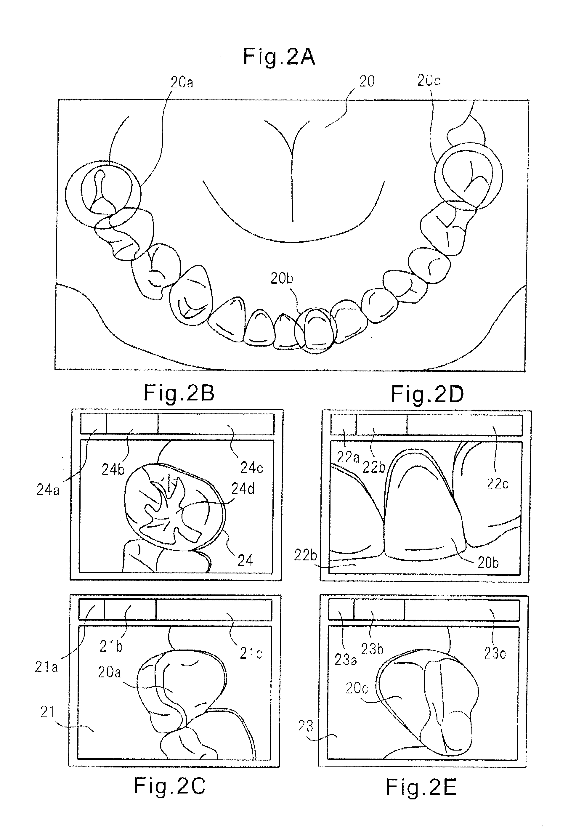
[0160]Next, another embodiment will be shown in FIG. 5 and explained. In the figure, reference numeral 51 indicates a wide range image inputting means. This is a means for capturing an image of all teeth of the upper jaw and all teeth of the lower jaw of the oral cavity. For example, it is possible to capture all teeth which are reflected in the convex mirror which is shown in FIG. 30 by a camera so as to obtain a wide range image or to continuously capture images shown in FIG. 6 and combine common parts from the still images forming the digital moving image so as to form a complete tooth image.

[0161]Reference numeral 52 indicates a tooth detecting means which extracts image data of respective teeth from the rows of teeth obtained by the wide range image inputting means 51. The extraction may, for example, be performed by a means using a contour extraction program to extract the peripheral sides in just a predetermined range to form an image of a single tooth and also by a means whi...


PUM


Abstract

A system configured provided with a continuously captured image sequence forming means for continuously capturing side surfaces of rows of teeth to form an image sequence, a side surface tooth row image forming means for combining sequences of images which were formed by the continuously captured image sequence forming means as partial tooth row images from an image forming the center of the overall composite so as to form a plurality of partial tooth row images, and a side surface tooth row image combining means for linking and combining a plurality of partial tooth row images which were formed by the side surface tooth row image forming means based on images farming the centers of the overall composite so as to form overall rows of teeth. By configuring the system in this way, it is possible to use a handheld type intraoral video camera to form a panoramic image of the side surface tooth rows for display on a computer monitor and propose a broad range of dental diagnosis and treatment to a patient and to secure participation of the patient in proactive dental diagnosis and treatment.

Description

TECHNICAL FIELD[0001]The present invention relates to a system which captures an image of the entire oral cavity and displays a panoramic image.BACKGROUND ART[0002]In the treatment of tooth cavities and other intraoral diseases, when the target treatment ends, the visits to the clinic usually also end. Treatment of tooth decay usually starts when the patient becomes aware of tooth pain, discomfort, or other symptoms. When the treatment ends, the visits to the clinic also end. This is the usual pattern. Therefore, even if there is other tooth decay, if there are no noticeable symptoms, in many cases it is left alone—the clinic is visited only after the tooth decay advances. Further, with such one-time visits to the clinic, a healthy oral cavity is not secured. Staining, swelling, loss, tartar, wear, salivary calculus, mismatch, and other issues for which there are no subjective symptoms, but which can be seen from the outside after often unnoticed by the person in question.[0003]For ...

Claims


Application Information

Patent Timeline
Patent Type & Authority Applications(United States)
IPC IPC(8): A61B1/04A61B1/24A61C19/04
CPCA61B1/04A61C19/04A61B1/24A61B1/0005A61B1/247A61B1/00087A61B1/00101A61B1/0607A61C9/0053A61B1/000094A61B1/000095
Inventor URAKABE, NOBUCHIKA
Owner ADVANCE CO LTD
Learn More