
Video phone

a technology of video phone and jack, which is applied in the direction of wireless commuication services, broadcast service distribution, instruments, etc., can solve the problems of reduced cost performance, design may be impaired in consideration of the balance with another part, and cost performance declines

Active Publication Date: 2009-06-30
NEC CORP
View PDF12 Cites 61 Cited by
  • Summary
  • Abstract
  • Description
  • Claims
  • Application Information

AI Technical Summary

Benefits of technology

"The present invention aims to provide a video phone that can display a user's face properly while keeping the cost low. The video phone has image sensing means that can capture the user's face and generate image information. The image sensing means can adjust the image information by enlarging or reducing the user's face. The video phone also has communication control means to transmit the adjusted image information to a communication partner. The technical effect of this invention is to improve the video phone's ability to display the user's face while maintaining low-cost performance."

Problems solved by technology

However, cost performance decreases when the infrared LED is mounted on a cell phone having the video phone function.
The design may be impaired in consideration of the balance with another part which forms the video phone apparatus.
However, as shown in FIG. 2 of reference 2, the illumination unit of the video phone set targets a very wide range, and cost performance decreases.
The design may be impaired in consideration of the balance with another part which forms the video phone set.
When the camera is mounted on a video phone, cost performance decreases.

Method used


Image

  • Video phone
  • Video phone
  • Video phone

Examples


Embodiment Construction

[0040]A video phone according to an embodiment of the present invention will be described in detail below with reference to the accompanying drawings.

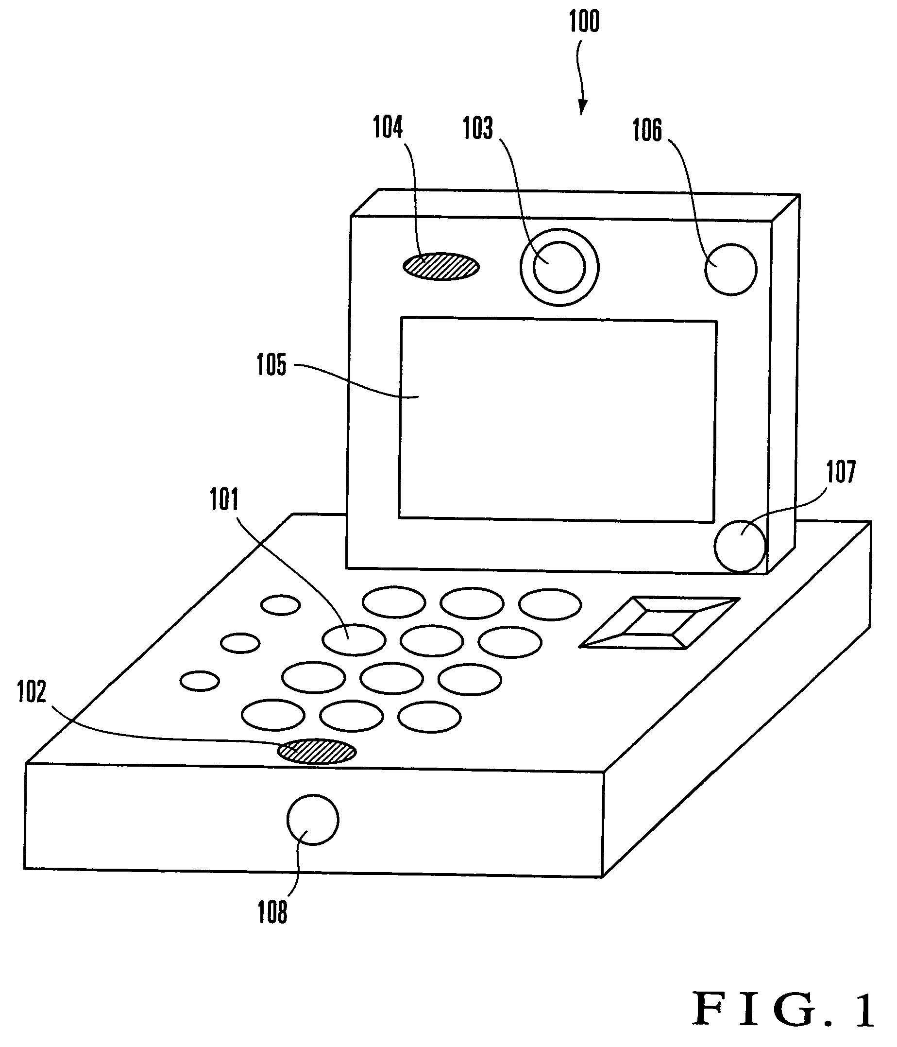
[0041]As shown in FIG. 1, the appearance of a video phone 100 according to the embodiment comprises an input button group 101, transmitter 102, camera 103, receiver 104, liquid crystal screen 105, mobile light 106, distance sensor 107, and illuminance sensor 108.

[0042]The input button group 101 includes buttons for setting figures, signs, and characters (e.g., alphabets), and buttons for setting predetermined control. The input button group 101 is used before telephone conversation, and if necessary, during telephone conversation. The input button group 101 functions as an input unit which accepts, e.g., an input for displaying an image based on image information generated by a control unit 109 (to be described later) on the liquid crystal screen 105, and an input for adjusting the volume of a sound output from the receiver 104.

[0043]T...


PUM


Abstract

A video phone includes an image sensing unit, face detection unit, image sensing adjustment unit, and communication control unit. The image sensing unit senses the face of a user serving as an object and generates image information. The image sensing unit has enlargement and reduction functions for the object in the image sensing range. The face detection unit detects the user's face from the image information generated by the image sensing unit. The image sensing adjustment unit sets, in the image information generated by the image sensing unit, a core area which has redundancy and contains a face area serving as an area corresponding to the face detected by the face detection unit. The image sensing adjustment unit controls the image sensing unit, and generates image information by performing at least one of enlargement and reduction processes on the core area under a predetermined condition. The communication control unit transmits the image information generated by the image sensing adjustment unit to a communication partner.

Description

BACKGROUND OF THE INVENTION[0001]The present invention relates to a video phone which adjusts an image display, volume output, and illumination lighting.[0002]To display the user's face at a proper size on the display of the partner's video phone during telephone conversation with the partner through the video phone, the distance between the user's face and a camera attached to the video phone must be kept constant.[0003]A volume output from the loudspeaker is kept constant regardless of the distance between the user and the video phone. To listen to the partner's voice at an appropriate volume, the user must manually adjust the volume.[0004]When the user's environment is dark, the image of the user that is transmitted to the partner's video phone becomes dark.[0005]Reference 1 (Japanese Patent Laid-Open No. 2002-165192) discloses a video phone apparatus which always generates proper video information regardless of the peripheral brightness of an object, and always effectively opera...

Claims


Application Information

Patent Timeline
Patent Type & Authority Patents(United States)
IPC IPC(8): G06K9/00H04N7/14H04N7/16H04W4/10
CPCH04N7/142H04N21/41407
Inventor MORI, KUNIHIKO
Owner NEC CORP
Learn More