Preparation method of surface composite coating for bottom plate of reduction furnace

A technology of surface compounding and reduction furnace, applied in the direction of coating, superimposed layer plating, metal material coating process, etc., can solve the problems of limited reduction furnace stable production, difficulty of reducing furnace chassis coating, loss of protection effect, etc. Achieve the effect of reducing the cost of raw materials, avoiding polysilicon pollution, and not easy to bulge and fall off.

Inactive Publication Date: 2019-11-12
江苏广研新材料技术有限公司
View PDF3 Cites 4 Cited by
  • Summary
  • Abstract
  • Description
  • Claims
  • Application Information

AI Technical Summary

Problems solved by technology

However, due to the complex porous structure of the polysilicon chassis, it is very difficult to prepare the coating on the chassis of the reduction furnace by traditional explosive soldering silver / stainless steel composite plates, and there is also the problem of high cost; if brush plating, thermal spraying, cold spraying and other methods are used directly on the chassis The silver coating prepared on the surface has low bonding strength and poor thermal shock performance. During the use of the reduction furnace, due to the high temperature in the furnace, corrosive atmosphere, gas scouring and cleaning operation of the reduction furnace, the silver coating will be destroyed, resulting in silver The coating dissipates quickly or falls off easily, thus losing the protective effect and having a short service life
It can be seen from the above that the defects of the pure silver coating limit the development of stable production of the reduction furnace. Therefore, a structurally stable chassis surface coating is developed to isolate the body material contamination in the chassis, thereby improving the purity of polysilicon and realizing polysilicon reduction. The stable production of high-purity electronic-grade polysilicon in furnaces is an urgent problem to be solved at present

Method used

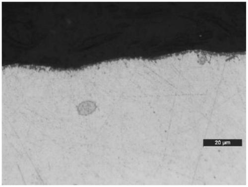
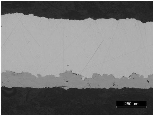
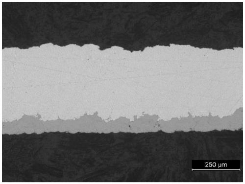

Image

  • Preparation method of surface composite coating for bottom plate of reduction furnace
  • Preparation method of surface composite coating for bottom plate of reduction furnace
  • Preparation method of surface composite coating for bottom plate of reduction furnace

Examples


Embodiment 1

[0038] A method for preparing a composite coating on the surface of a reduction furnace chassis, comprising the following steps:

[0039] (1) Surface treatment: Grind the surface of the reduction furnace chassis with 800# sandpaper, then clean it with acetone, and finally dry the chassis surface with compressed air to remove grease and other impurities on the chassis surface;

[0040](2) The diameter of the reduction furnace chassis is 1.8m, and supporting protective fixtures and spraying auxiliary equipment are installed to ensure that the reduction furnace chassis is not damaged and polluted during the coating preparation process;

[0041] (3) Supersonic flame spraying is used to prepare a layer of bonding layer on the surface of the chassis that has been treated; the thickness of the bonding layer is 2 μm, the porosity is less than 1%, and the bonding strength> 35MPa; the raw material of the bonding layer is Ni powder, the average particle size of the raw material is 20μm, ...

Embodiment 2

[0047] A method for preparing a composite coating on the surface of a reduction furnace chassis, comprising the following steps:

[0048] (1) Surface treatment: Grind the surface of the reduction furnace chassis with 800# sandpaper, then clean it with acetone, and finally dry the chassis surface with compressed air to remove grease and other impurities on the chassis surface;

[0049] (2) The diameter of the reduction furnace chassis is 1.8m, and supporting protective fixtures and spraying auxiliary equipment are installed to ensure that the reduction furnace chassis is not damaged and polluted during the coating preparation process;

[0050] (3) adopt supersonic flame spraying to prepare one layer of bonding layer on the chassis surface that has done surface treatment; Bonding layer thickness is 50 μ m, porosity is less than 1%, bonding strength>35MPa; The raw material of described bonding layer is NiCr powder, the average particle size of the raw material is 150 μm, and the ...

Embodiment 3

[0056] A method for preparing a composite coating on the surface of a reduction furnace chassis, comprising the following steps:

[0057] (1) Surface treatment: Grind the surface of the reduction furnace chassis with 800# sandpaper, then clean it with acetone, and finally dry the chassis surface with compressed air to remove grease and other impurities on the chassis surface;

[0058] (2) The diameter of the reduction furnace chassis is 1.8m, and supporting protective fixtures and spraying auxiliary equipment are installed to ensure that the reduction furnace chassis is not damaged and polluted during the coating preparation process;

[0059] (3) Supersonic flame spraying is used to prepare a layer of adhesive layer on the surface of the surface treated chassis; the thickness of the adhesive layer is 1000 μm, the porosity is less than 1%, and the bonding strength> 35MPa; the raw material of the adhesive layer is Ti powder, the average particle size of the raw material is 250 μ...


PUM

PropertyMeasurementUnit
particle sizeaaaaaaaaaa
thicknessaaaaaaaaaa
particle sizeaaaaaaaaaa

Abstract

The invention discloses a preparation method of a surface composite coating for a bottom plate of a reduction furnace. The preparation method of the surface composite coating for the bottom plate of the reduction furnace comprises the following steps of preparing a bonding layer: adopting hot spraying for preparing a layer of bonding layer on the inner surface of a stainless steel bell jar, wherein the bonding layer is prepared from one of raw materials: Ni, Ti, Cu, Fe, Zn, C-Co, WC-10Co4Cr, MCrAIY, a high-entropy alloy, NiTi, NiCr and stainless steel; and preparing an antifouling coating: utilizing gas power spraying for preparing the antifouling coating with high compactness, high bonding strength and high heat stability on the surface of the bonding layer, wherein the antifouling coating is prepared from a raw material which is silver powder. According to the preparation method, on one hand, the process step can be simplified, and the production cost is reduced; and on the other hand, the structure stability of the coating can be improved, and the service life of the coating is prolonged.

Description

technical field [0001] The invention belongs to the technical field of polysilicon production equipment, and in particular relates to a method for preparing a composite coating on the surface of a reduction furnace chassis. Background technique [0002] The improved Siemens method is the mainstream technology for producing polysilicon in the world. Its working principle is to use high-purity hydrogen to reduce silicon-containing gas (commonly used silicon-containing gases are high-purity trichlorosilane and silane) on high-purity silicon cores at about 1100 ° C to generate polysilicon. And deposited on the silicon core, the product is finally mined from the reduction furnace bell in the form of polycrystalline silicon rods. The polysilicon reduction furnace is the main equipment for the production of the improved Siemens method, and it is also the most critical equipment for the production of high-purity polysilicon. At present, there are many types of general-purpose react...

Claims


Application Information

Patent Timeline
Patent Type & Authority Applications(China)
IPC IPC(8): C23C4/01C23C4/129C23C24/04C23C28/02
CPCC23C24/045C23C28/021C23C4/01C23C4/129
Inventor 谢迎春黄仁忠黄健曾良王帅张科杰吴晓涛
Owner 江苏广研新材料技术有限公司
Why Eureka
Try Eureka