


Quick Research
Generate reliable direction feasibility study reports for your R&D in just a few steps.

Technical Q&A
Discover and master advanced knowledge NOW. Basics, ideas, possibilities, all at once.

Find Solutions
As an expert in R&D theories, this can generate solutions to your technical problems instantly.

Evaluate Feasibility
Analyze your overall solution with one click, know your potential R&D risks in advance.

Monitor Landscape
Get weekly tech updates, stay abreast of the latest tech innovations and key insights.
Ceramic catalysis filter pipe
A technology of filter tubes and ceramics, which is applied in the field of ceramic catalytic filter tubes, can solve the problems of complex structure, large footprint, and low dust removal efficiency, and achieve the effects of good filtering effect, wide denitrification temperature range, and strong wear resistance
- Summary
- Abstract
- Description
- Claims
- Application Information
AI Technical Summary
Problems solved by technology
Method used
Image


Examples
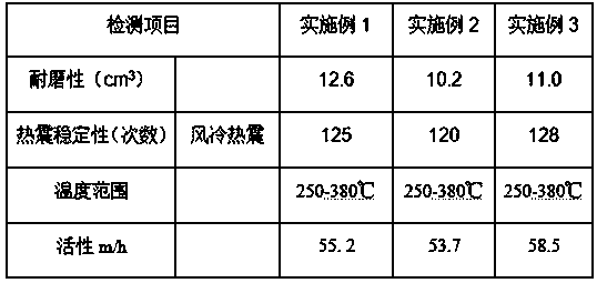
Embodiment 1
[0024] 1) Mud mixing: Put attapulgite in 7mol / L HCl solution, stir at 80°C for 8 hours, wash and dry, and grind to 400 mesh. Dry mix 22 parts of modified attapulgite, 28 parts of anatase titanium dioxide, 2 parts of γ-alumina, 4 parts of silicon dioxide, and 1 part of tungsten trioxide, add 2 parts of cerium nitrate, metavanadic acid 2 parts of ammonium, 3 parts of manganese nitrate solution with a volume ratio of 50%, and deionized water to prepare a slurry. Add the prepared ammonium metavanadate solution and cerium nitrate solution to the above slurry and stir evenly. The evaporator evaporates under reduced pressure to remove water. Calcinate the completely dried material at a high temperature of 500°C to activate the activity, grind it to 400 mesh, and obtain a catalyst powder; mix 50 parts of catalyst powder, 2 parts of calcium oxide, 2 parts of magnesium oxide, and 0.2 parts of polycarboxylate superplasticizer , 3 parts of carboxymethyl cellulose, 2 parts of stearic acid...
Embodiment 2
[0030] 1) Mud mixing: Put attapulgite in 6mol / L HCl solution, stir at 80°C for 8 hours, wash and dry, and grind to 400 mesh. Dry mix 30 parts of modified attapulgite, 30 parts of anatase titanium dioxide, 3 parts of γ-alumina, 5 parts of silicon dioxide, and 1.5 parts of tungsten trioxide, add 3 parts of cerium nitrate, metavanadic acid 3 parts of ammonium, 6 parts of manganese nitrate solution with a volume ratio of 50%, and deionized water to prepare a slurry. Add the prepared ammonium metavanadate solution and cerium nitrate solution to the above slurry and stir evenly. The evaporator evaporates under reduced pressure to remove water. Calcinate the completely dried material at a high temperature of 500°C to activate the activity, grind it to 400 mesh, and obtain a catalyst powder; mix 80 parts of catalyst powder, 3 parts of calcium oxide, 3 parts of magnesium oxide, and 0.3 parts of polycarboxylate superplasticizer , 7 parts of carboxymethyl cellulose, 3 parts of stearic a...
Embodiment 3
[0036] 1) Mud mixing: Put attapulgite in 6mol / L HCl solution, stir at 80°C for 8 hours, wash and dry, and grind to 400 mesh. Dry mix 25 parts of modified attapulgite, 25 parts of anatase titanium dioxide, 2 parts of γ-alumina, 4 parts of silicon dioxide, and 1.5 parts of tungsten trioxide, add 2 parts of cerium nitrate, metavanadic acid 3 parts of ammonium, 5 parts of manganese nitrate solution with a volume ratio of 50%, and deionized water to prepare a slurry. Add the prepared ammonium metavanadate solution and cerium nitrate solution to the above slurry and stir evenly. The evaporator evaporates under reduced pressure to remove water. Calcinate the completely dried material at a high temperature of 500°C to activate the activity, grind it to 400 mesh, and obtain a catalyst powder; mix 65 parts of catalyst powder, 3 parts of calcium oxide, 2 parts of magnesium oxide, and 0.2 parts of polycarboxylate superplasticizer , 5 parts of carboxymethyl cellulose, 2 parts of stearic a...
PUM
| Property | Measurement | Unit |
|---|---|---|
| particle diameter | aaaaa | aaaaa |
| pore size | aaaaa | aaaaa |
| pore size | aaaaa | aaaaa |
Abstract
Description
Claims
Application Information
 - R&D Engineer
- R&D Manager
- IP Professional
- Industry Leading Data Capabilities
- Powerful AI technology
- Patent DNA Extraction
Browse by: Latest US Patents, China's latest patents, Technical Efficacy Thesaurus, Application Domain, Technology Topic, Popular Technical Reports.
© 2024 PatSnap. All rights reserved.Legal|Privacy policy|Modern Slavery Act Transparency Statement|Sitemap|About US| Contact US: help@patsnap.com