Joint material, semiconductor device and manufacturing method of semiconductor device
A technology for bonding materials and semiconductors, which is applied in the fields of semiconductor/solid-state device manufacturing, semiconductor devices, and semiconductor/solid-state device components, etc. It can solve the problems of low operating temperature, inability to effectively release high internal stress, and low bonding reliability. The effect of low manufacturing cost, buffering internal stress, and improving bonding reliability
- Summary
- Abstract
- Description
- Claims
- Application Information
AI Technical Summary
Problems solved by technology
Method used
Image
Examples
Embodiment 1
[0070] A method of manufacturing a semiconductor device, comprising the steps of:
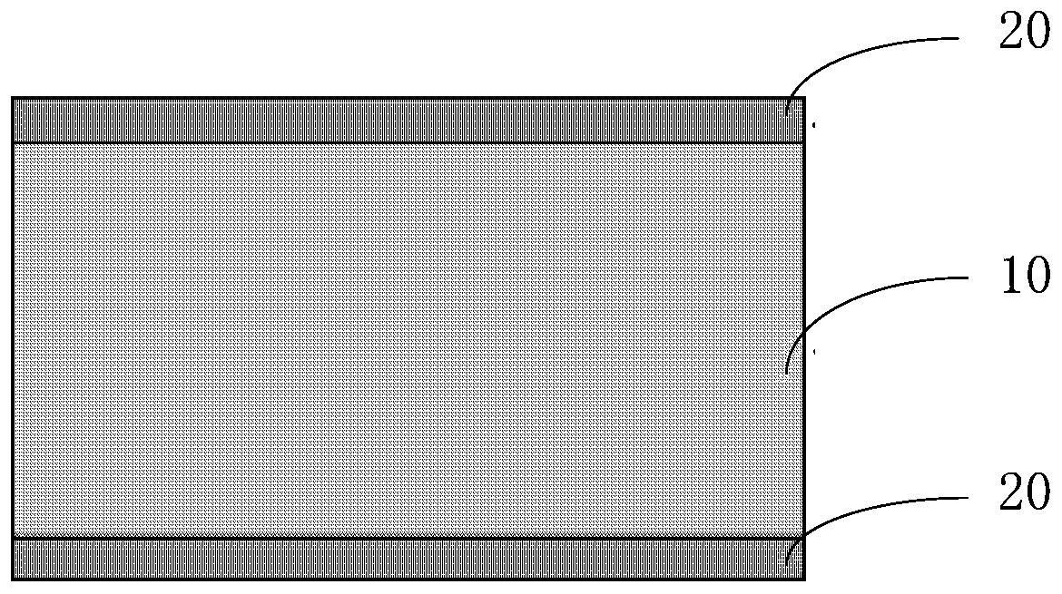
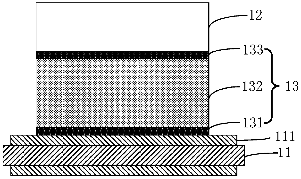
[0071] S10. Provide a first substrate with metal copper layers on both sides of the surface, and set a bonding material A on the metal copper layer on one side surface of the first substrate. The bonding material A includes a porosity of 10%, and a thickness of A foamed copper support layer of 5 μm and a SAC305 solder layer with a thickness of 5 μm arranged on the opposite side surfaces of the foamed copper support layer; and then semiconductor chips, resistors, capacitors, and connecting columns are arranged on the bonding material A , terminal, and then in an inert gas atmosphere, the first bonding process is performed at a bonding temperature of 250 ° C. The SAC305 solder reacts with the metallic copper layer of the first substrate and the foamed copper of the supporting layer to form a high melting point intermetallic compound Cu. 3 Sn, and SAC305 solder react with metal (such as silver) on...
Embodiment 2
[0075] A method of manufacturing a semiconductor device, comprising the steps of:
[0076] S10. Provide a first substrate with metal copper layers on both sides of the surface, and set a bonding material B on the metal copper layer on one side surface of the first substrate. The bonding material B includes a porosity of 10%, and a thickness of A foamed copper support layer of 10 μm, a reaction layer copper layer with a thickness of 2 μm arranged on opposite sides of the support layer, and a Sn-0.7Cu solder layer with a thickness of 5 μm arranged on the reaction layer; and then the semiconductor chip , resistors, capacitors, connecting columns, and terminals are arranged on the bonding material B, and then the first bonding process is carried out in an inert gas atmosphere at a bonding temperature of 250°C, and the Sn-0.7Cu solder and the metallic copper layer of the first substrate , the reaction layer copper layer reacts to form a high melting point intermetallic compound Cu ...
Embodiment 3
[0080] A method of manufacturing a semiconductor device, comprising the steps of:
[0081] S10. Provide a first substrate with metal copper layers on both sides of the surface, and set a bonding material C on the metal copper layer on one side surface of the first substrate. The bonding material C includes a porosity of 10%, and a thickness of A foamed nickel support layer of 10 μm, a reaction layer nickel layer with a thickness of 2 μm arranged on the opposite sides of the support layer, and a Sn-0.7Cu solder layer with a thickness of 5 μm arranged on the reaction layer; and then the semiconductor chip , resistors, capacitors, connecting columns, and terminals are arranged on the bonding material C, and then the first bonding process is performed in an inert gas atmosphere at a bonding temperature of 250°C, and the Sn-0.7Cu solder and the metallic copper layer of the first substrate , the reaction layer nickel layer reacts to form a high melting point intermetallic compound C...
PUM
| Property | Measurement | Unit |
|---|---|---|
| Porous aperture | aaaaa | aaaaa |
| Thickness | aaaaa | aaaaa |
| Thickness | aaaaa | aaaaa |
Abstract
Description
Claims
Application Information
 - R&D
- Intellectual Property
- Life Sciences
- Materials
- Tech Scout
- Unparalleled Data Quality
- Higher Quality Content
- 60% Fewer Hallucinations
Browse by: Latest US Patents, China's latest patents, Technical Efficacy Thesaurus, Application Domain, Technology Topic, Popular Technical Reports.
© 2025 PatSnap. All rights reserved.Legal|Privacy policy|Modern Slavery Act Transparency Statement|Sitemap|About US| Contact US: help@patsnap.com


