
Vortex machine

A vortex machine and vortex cavity technology, applied in centrifuges, cyclone axial reversible devices, cyclone devices, etc., can solve the problems of high cost of seawater desalination, easy aging of catalysts, waste of energy, etc. Equipment operation efficiency, the effect of cheap seawater desalination

Inactive Publication Date: 2019-04-05
陈久斌
View PDF0 Cites 1 Cited by
  • Summary
  • Abstract
  • Description
  • Claims
  • Application Information

AI Technical Summary

Problems solved by technology

[0003] Existing vacuuming equipment has unsatisfactory vacuuming effect, high noise, and dust particle pollution. It is troublesome to deal with dust after dust removal
[0004] The existing range hoods cannot separate the fumes, which makes it troublesome to clean the range hoods and pollutes the environment with the fume particles. The fume particles have become another important source of urban air pollution.
[0005] The existing sewage treatment equipment is complex, the cost is too high, the cost of sewage treatment is too high, and the treatment effect is mediocre. Sewage treatment has become the top priority of environmental treatment
[0006] The cost of existing oxygen production equipment is too high, and the cost of oxygen production is too high to achieve popularization and application, so that pure oxygen combustion cannot be realized, resulting in a large amount of nitrogen oxide emissions to form an important source of pollution
[0007] Existing water purifiers mainly use methods such as filtration and water purifiers, which generally have defects such as failure to meet higher drinking water standards and high water purification costs.
[0008] The existing seawater desalination equipment is complicated, the cost is too high, the cost of seawater desalination is too high, and the energy consumption is too large
Existing marine chemical equipment is complicated and expensive, and the effect on the utilization of marine resources is not ideal
[0009] Existing separation equipment mainly includes centrifuges, etc., which generally have defects such as general separation effect and high energy consumption.
[0010] The existing beneficiation equipment has a general beneficiation effect and cannot achieve finer separation, resulting in waste of resources and environmental pollution
[0011] Existing oil refining equipment generally adopts high-temperature distillation cracking method, which has high refining cost and high energy consumption. High temperature seriously damages the macromolecules in crude oil, producing a large amount of petroleum gas and petroleum residue, which greatly reduces the oil yield and the output of high-quality oil.
Lead, heavy metals, heavy elements, etc. in the oil cannot be removed, causing serious fuel pollution
[0012] Existing coal preparation equipment is only for simple coal washing, which cannot fully clean the coal, resulting in the formation of sulfur dioxide after the sulfur in the coal is burned, and various metal elements in the coal. The radioactive elements in the coal also escape into the atmosphere and coal ash, causing serious environmental pollution and waste of resources
[0013] The current nuclear fuel is mainly selected by a centrifuge, which is too expensive and the selection is not clean, causing environmental pollution and waste of resources.
Nuclear waste and nuclear sewage are basically impossible to treat, posing a serious environmental threat
[0014] Existing waste treatment technologies generally use incineration, landfill, etc., and the tail gas treatment after incineration is not clean, causing serious air pollution, and landfill causes land occupation and groundwater pollution
[0015] Existing mud dehydration has a variety of equipment, generally the dehydration is not clean, and it is difficult to dehydrate ultra-fine mud
[0016] Existing oil and gas recovery equipment generally has problems such as high cost and incomplete oil and gas recovery
[0017] Existing reactor equipment includes reactors, catalyst reaction tanks or towers, etc., which generally have defects such as slow reaction speed, incomplete reaction, high cost, and easy aging of catalysts.
[0018] Existing boiler equipment, burner equipment, etc. generally have insufficient combustion, especially the burnout rate of coal-fired boilers is only about 80%, resulting in serious energy waste and serious environmental pollution caused by insufficient combustion
[0019] Existing kilns include shaft kilns, rotary kilns, incinerators, reaction furnaces, etc., which generally have defects such as insufficient combustion, high energy consumption, low efficiency, and large volume.
[0020] Existing grinding equipment includes pulverizers, Raymond mills, wind-swept mills, etc., which generally suffer from high energy consumption, low grinding powder efficiency, and difficulty in preparing ultra-fine powders and nano-powders.
[0021] There are no good methods and equipment for molecular decomposition. Generally, electrolysis is used, which consumes a lot of energy. Electrolysis is generally used for water molecule decomposition. The energy consumption and cost are too high, so that hydrogen energy cannot be better used.
CO2 is basically unable to be treated, resulting in a large amount of greenhouse gas emissions. Some organic waste gas treatment uses photon decomposition, which generally has poor effects and high energy consumption.

Method used


Image

  • Vortex machine
  • Vortex machine
  • Vortex machine

Examples


Embodiment Construction

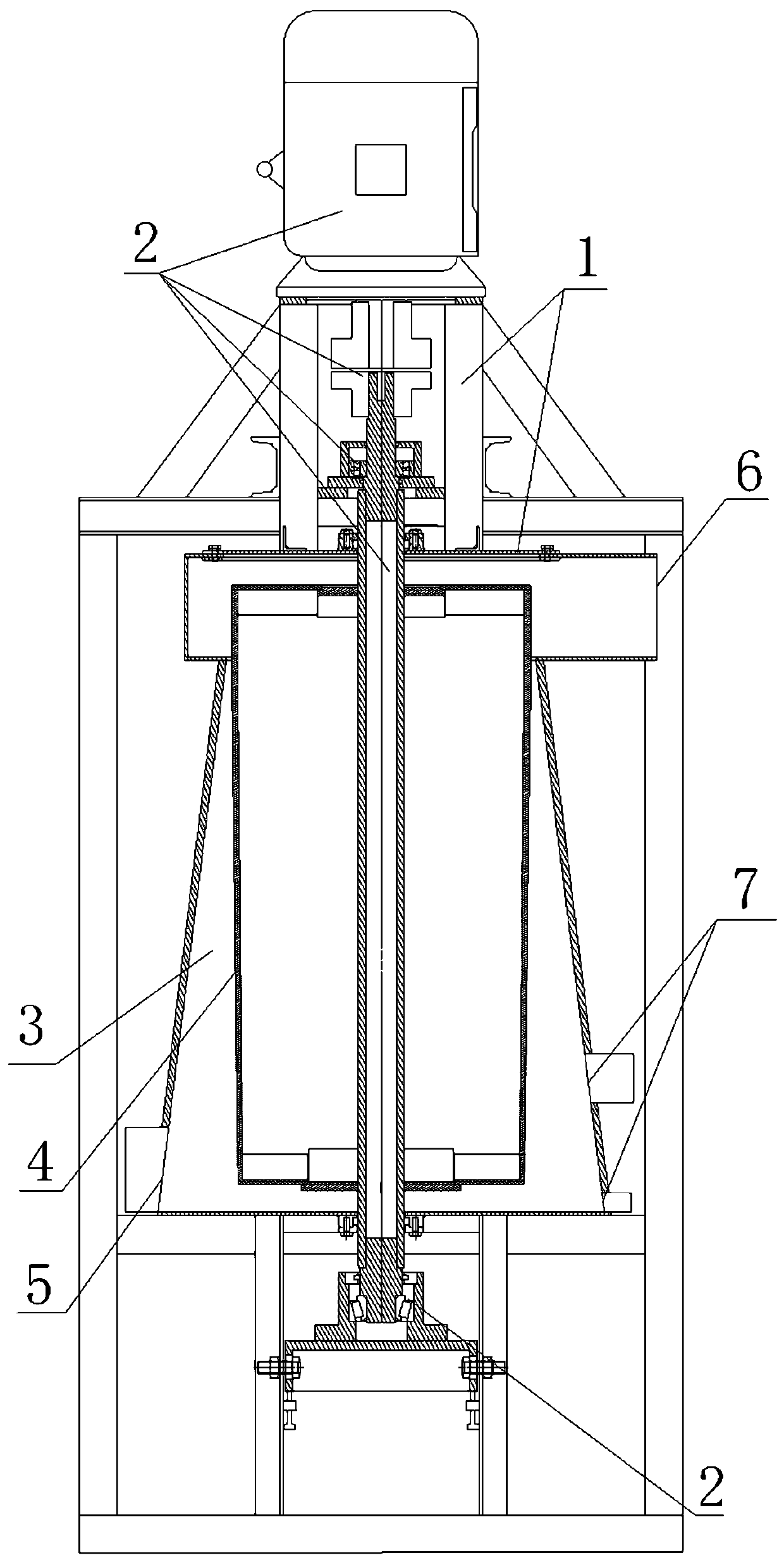
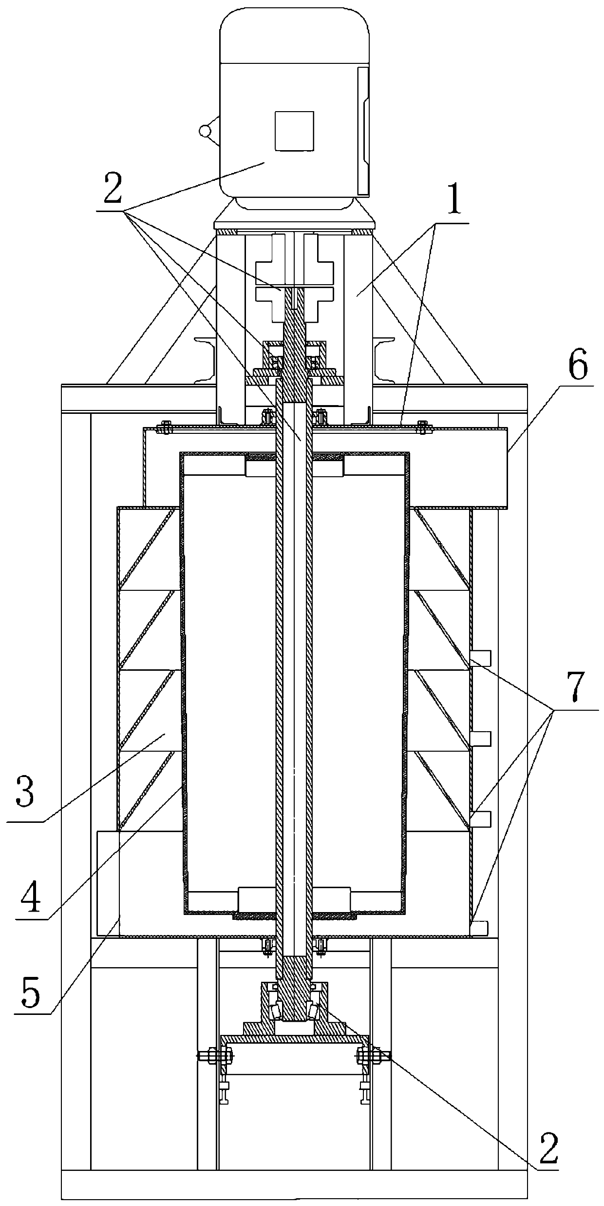
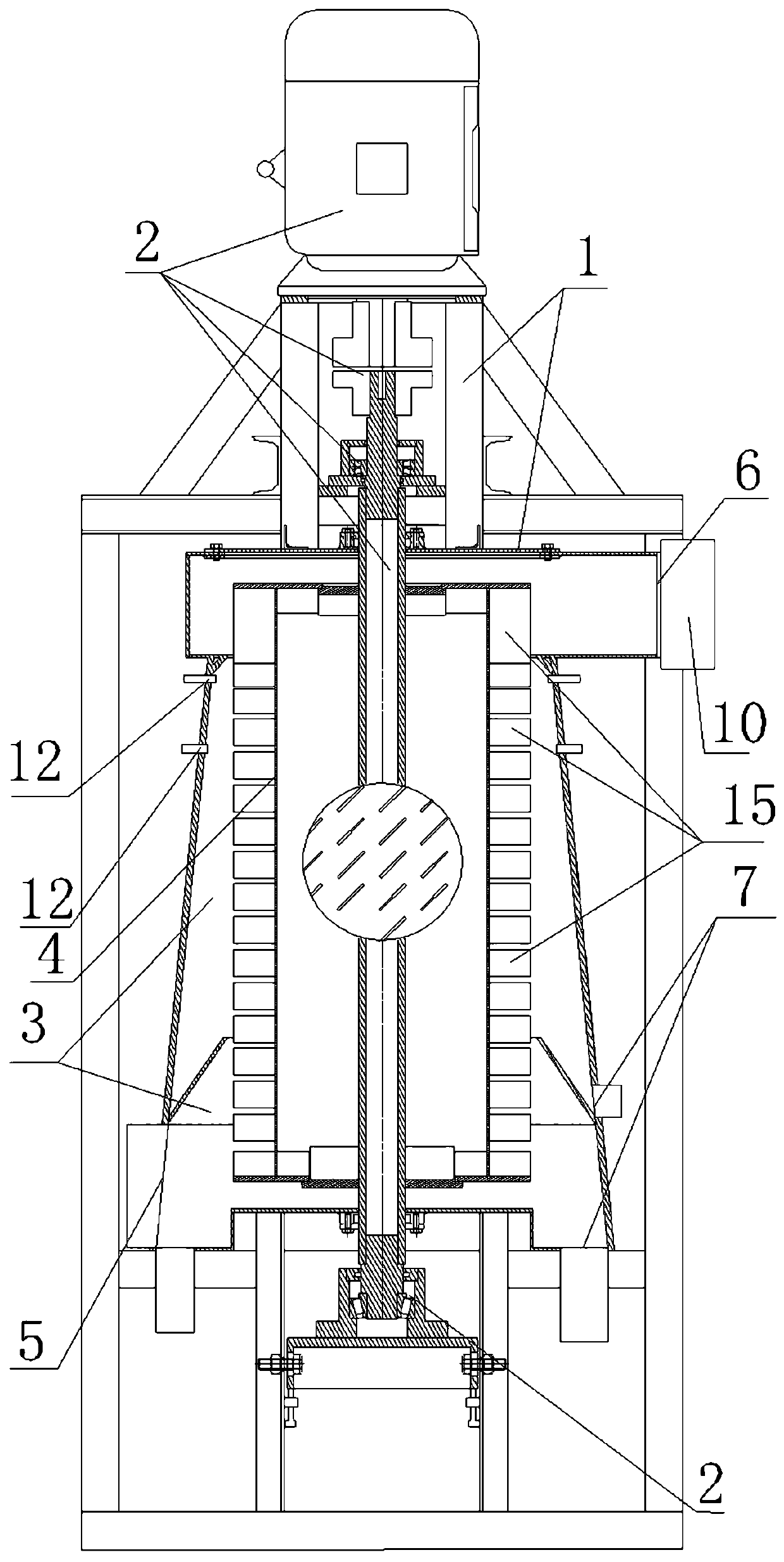
[0062] The main structure of the vortex machine includes a housing 1 and a transmission device 2. The transmission device 2 is arranged on the housing 1. The vortex chamber 3 is arranged in the housing 1. The transmission body 4 with the outer periphery as the working surface is arranged in the vortex chamber 3. The transmission device 2 and The transmission body 4 is connected. When the transmission device 2 drives the transmission body 4 to rotate, the outer periphery of the transmission body 4 drives the working medium to rotate and flow in the eddy current chamber 3 around the transmission body 4. One end of the eddy current chamber 3 is provided with the eddy current chamber inlet 5, and the other end of the eddy current chamber 3 is provided with Outlet 6 of the vortex chamber, at least one section of the vortex chamber 3 has a circular cross-section and its inner diameter gradually narrows toward the outlet 6 of the vortex chamber, and at least one discharge port 7 is pro...


PUM


Abstract

The invention discloses a vortex machine. The vortex machine includes a shell body and a transmission device; the transmission device is arranged on the shell body, a vortex current cavity is formed in the shell body, a transmission body with a working face of the outer periphery is arranged in the vortex current cavity, the transmission device is connected with the transmission body, when the transmission device drives the transmission body to rotate, the outer periphery of the transmission body drives a working medium to rotate and flow in the vortex current cavity at the periphery of the transmission body, and a vortex current cavity inlet is formed in one end of the vortex current cavity; and a vortex current cavity outlet is formed in the other end of the vortex current cavity, the inner diameter of at least one section of the vortex current cavity is gradually reduced towards the vortex current cavity outlet end, and at least one discharging opening is formed in the periphery ofthe vortex current cavity. The vortex machine can be widely used in the fields such as dust removal, desulfurization, de-nitrification, smoke removal, deodorization, vehicle and ship exhaust purification, oil smoke extraction, air purification, oil and gas recovery, waste disposal, nuclear waste treatment, powder selection, mineral processing, seawater desalination, sewage treatment, water purification, refining, oxygen production, reactors, boilers, burners, and grinding equipment, can achieve high degree purification of flue, can solve the air pollution and water pollution, and can prepare avariety of powders such as ultrafine powder and nano-powder.

Description

technical field [0001] The invention relates to sewage treatment, water purification, seawater desalination, marine chemical industry, ore dressing, coal preparation, nuclear waste treatment, oil refining, oil and gas recovery, garbage treatment, mud dehydration, air purification, dust removal, dust suction, desulfurization, denitrification, and oil fume purification , tail gas treatment, black smoke removal, odor removal, oxygen production, air separation extraction, chemical reactor, boiler, burner, kiln, reaction furnace, grinding, powder preparation, molecular decomposition, water decomposition hydrogen production, decomposition of CO2 , decomposition of SO2, decomposition of odorous gas molecules and other fields, specifically a vortex machine, which can realize functions such as grinding, chemical reaction, separation, molecular decomposition, etc. Various functions can be used alone or in combination, and at the same time, it can realize fluid transportation . Backgro...

Claims


Application Information

Patent Timeline
Patent Type & Authority Applications(China)
IPC IPC(8): B04C5/081B04C11/00
CPCB04B5/12B04C5/081B04C11/00
Inventor 陈久斌
Owner 陈久斌
Learn More