
Method and system for preparing ultrathin metal lithium films through magnetron sputtering

An ultra-thin metal, magnetron sputtering technology, applied in sputtering coating, metal material coating process, ion implantation coating and other directions, can solve the problem of unfavorable current uniform distribution, small specific surface area of ​​metal lithium negative electrode, and uneven surface and other problems, to achieve the effect of improving volume energy density and safety, uniform surface current density distribution, and uniform and smooth surface

Inactive Publication Date: 2019-03-01
重庆天齐锂业有限责任公司
View PDF14 Cites 17 Cited by
  • Summary
  • Abstract
  • Description
  • Claims
  • Application Information

AI Technical Summary

Problems solved by technology

At present, the traditional commercial lithium metal strip negative electrode preparation method is mostly prepared by mechanical extrusion technology. This method is to physically press the metal lithium ingot to make it thin. However, due to the limitations of equipment and technical principles, this method The thickness of the lithium ribbon prepared by the technology is basically about 100 μm, and it is difficult to prepare a metal lithium thin film with a thickness of less than 50 μm
If it is used as a lithium metal negative electrode material, it is too thick, which is not conducive to the improvement of the volume energy density of lithium secondary batteries, and is also not conducive to the miniaturization and thinning of batteries.
In addition, the metal lithium anode prepared by this simple mechanical method has a small specific surface area, and the surface is not smooth enough, which is not conducive to the uniform distribution of current. These defects may lead to the formation of metal lithium dendrites during charging and discharging, and eventually lead to safety accidents.
[0004] So far, there is no report on the preparation of ultra-thin lithium metal films by magnetron sputtering technology.

Method used


Image

  • Method and system for preparing ultrathin metal lithium films through magnetron sputtering

Examples


Embodiment 1

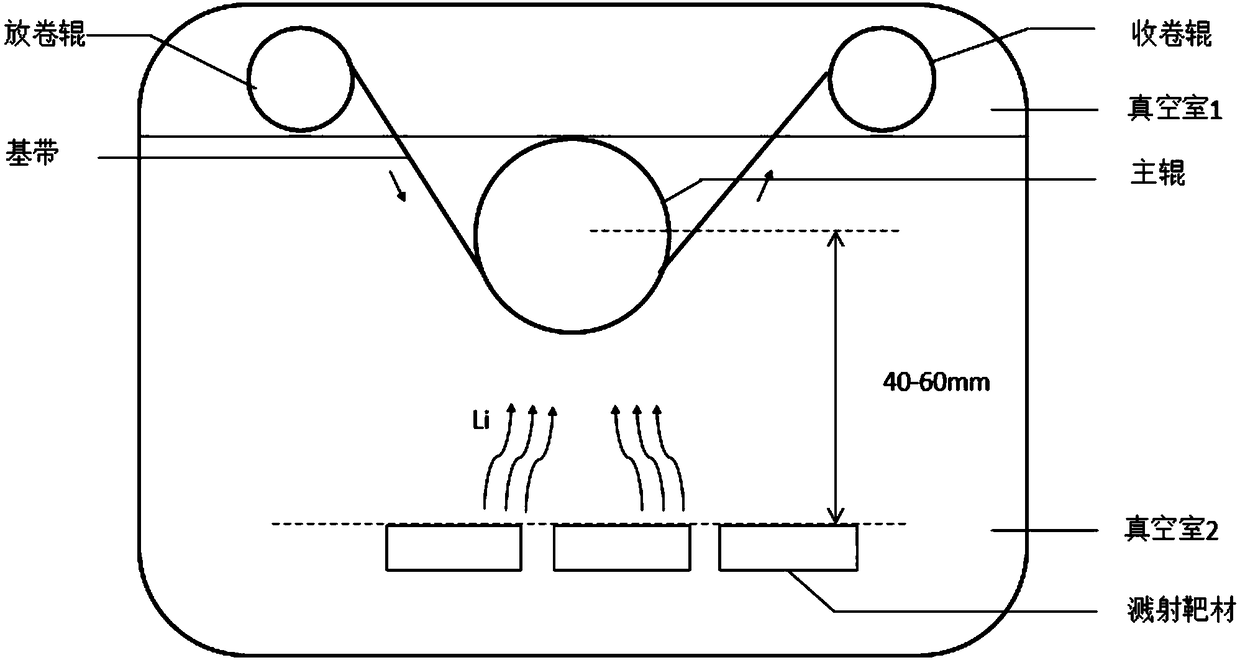
[0062] The flexible substrate to be sputtered used in this embodiment is a metal copper foil with a thickness of 20 μm. Prepare battery-grade lithium metal into the required target shape and put it in the sputtering studio. The vacuum degree of vacuum chamber 2 reaches 1×10 -4 After Pa, the DC magnetron sputtering system was turned on, the power was 50W, and the current was 3A. Unwind roll at 1m min -1 The copper foil is sent out at a constant speed. During the sputtering process, the working pressure of the vacuum chamber 2 is 1Pa, and the pressure of the winding chamber (vacuum chamber 1) is 6×10 -1 Pa. Argon flow is 10cm 3 s -1 , The target base distance (the distance from the target to the center of the main roller) is 60mm, the substrate temperature is 60℃, and the deposition time is 1min. After testing, the thickness of the metal lithium film after sputtering is 10 μm ± 1 μm.

Embodiment 2

[0064] The flexible substrate to be sputtered used in this embodiment is a high temperature resistant polyester film (PET film) with a thickness of 30 μm. Prepare battery-grade lithium metal into the required target shape and put it in the sputtering studio. The vacuum degree of vacuum chamber 2 reaches 1×10 -3 After Pa, turn on the DC magnetron sputtering system with a power of 30W and a current of 1A. Unwind roller at 0.4m min -1 The PET film is sent out at a constant speed. The working pressure of vacuum chamber 2 during sputtering is 5×10 -1 Pa, the pressure of the winding chamber (vacuum chamber 1) is 2×10 -1 Pa. Argon flow is 40cm 3 s -1 , The target base distance (the distance from the target to the center of the main roller) is 40mm, the substrate temperature is 80°C, and the deposition time is 10min. After testing, the thickness of the metal lithium film after sputtering is 20μm±1μm.

Embodiment 3

[0066] The flexible substrate to be sputtered used in this embodiment is a metal copper foil with a thickness of 6 μm. The surface treatment of 6μm copper foil by radio frequency plasma is carried out in advance, and the treatment time is 2min. Prepare battery-grade lithium metal into the required target shape and put it in the sputtering studio. The vacuum degree of vacuum chamber 2 reaches 8×10 -4 After Pa, the DC magnetron sputtering system was turned on, the power was 35W, and the current was 2A. Unwind roller at 0.8m min -1 The copper foil is sent out at a constant speed. The working pressure of vacuum chamber 2 during sputtering is 6×10 -1 Pa, the pressure of the winding chamber (vacuum chamber 1) is 5×10 -1 Pa. Argon flow rate is 15cm 3 s -1 , The target base distance (the distance from the target to the center of the main roller) is 50mm, the substrate temperature is 70℃, and the deposition time is 5min. After testing, the thickness of the metallic lithium film after...


PUM

PropertyMeasurementUnit
thicknessaaaaaaaaaa
thicknessaaaaaaaaaa
thicknessaaaaaaaaaa

Abstract

The invention discloses a method and a system for preparing ultrathin metal lithium films through magnetron sputtering. The method includes at least putting base materials and metal lithium targets into a vacuum environment, and depositing the ultrathin metal lithium films on the base materials according to a direct-current magnetron sputtering method. The system comprises a direct-current magnetron sputtering device, at least one unwinding mechanism, at least one winding mechanism and at least one main roller. The unwinding mechanisms and the winding mechanisms are matched with each other, and are arranged in a first vacuum chamber, and the main rollers are arranged in a second vacuum chamber. The method and the system have the advantages that the metal lithium films deposited by the magnetron sputtering technology are thinner and have uniform and smooth surfaces and high adhesion to the base materials; when the metal lithium films serve as negative electrode materials of lithium secondary batteries, the surface current density distribution can be uniform, formation of lithium dendrites can be reduced, the electrochemical performance of the batteries can be improved, and the cyclelife of the batteries can be prolonged.

Description

Technical field [0001] The invention relates to a method for preparing an ultra-thin metal lithium film, in particular to a method and a system for preparing an ultra-thin metal lithium film by magnetron sputtering, and belongs to the technical field of lithium ion batteries. Background technique [0002] In the early lithium secondary batteries, the metal lithium negative electrode continuously produced "lithium dendrites" and penetrated the diaphragm during the cycle, which caused the battery's positive and negative electrodes to short-circuit, which caused various safety problems. In order to avoid the above problems, since the 1990s, lithium-ion secondary batteries (theoretically no metal lithium is generated during battery charging and discharging) have gradually replaced metal lithium secondary batteries. However, the current technology to increase the actual specific capacity of lithium-ion battery positive and negative materials has entered a bottleneck, and cannot meet t...

Claims


Application Information

Patent Timeline
Patent Type & Authority Applications(China)
IPC IPC(8): C23C14/35C23C14/14C23C14/56
CPCC23C14/14C23C14/35C23C14/562
Inventor 邹崴聂阳曹乃珍
Owner 重庆天齐锂业有限责任公司
Learn More