In-situ Oxygen Generation Ozone Enhanced Three-stage Electrochemical Water Treatment Equipment and Water Treatment Method

A kind of water treatment equipment, electrochemical technology, applied in the direction of oxidation water/sewage treatment, water/sewage treatment equipment, chemical instruments and methods, etc., can solve the problem of low oxidation reaction rate, slow mass transfer of reaction system, pollution of atmospheric environment, etc. problems, to achieve the effect of streamlining equipment, improving processing energy efficiency, and high processing efficiency

Active Publication Date: 2021-12-07
HOHAI UNIV
View PDF7 Cites 0 Cited by
  • Summary
  • Abstract
  • Description
  • Claims
  • Application Information

AI Technical Summary

Problems solved by technology

The aeration efficiency of ozonated gas through the porous aeration head is low, and the residual ozone in the tail gas needs to be quenched, otherwise it will pollute the atmospheric environment
In traditional electrochemical reactors, the mass transfer of the reaction system is slow, there are dead angles, and the efficiency is low
The reaction rate of oxides in the reaction solution is low, the reaction time is long, the required equipment is large, and if the effluent contains a high concentration of residual oxides, it needs to be further quenched

Method used


Image

  • In-situ Oxygen Generation Ozone Enhanced Three-stage Electrochemical Water Treatment Equipment and Water Treatment Method
  • In-situ Oxygen Generation Ozone Enhanced Three-stage Electrochemical Water Treatment Equipment and Water Treatment Method
  • In-situ Oxygen Generation Ozone Enhanced Three-stage Electrochemical Water Treatment Equipment and Water Treatment Method

Examples


Embodiment 1

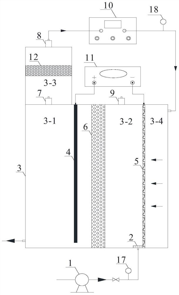
[0033] A three-stage electrochemical water treatment equipment for in-situ oxygen generation and ozone enhancement, such as figure 1 As shown, comprise water inlet device 1 (in the present embodiment, be water inlet pump), reaction device 3, oxygen storage chamber 3-3, and be located at the anode 4 inside reaction device 3, negative electrode 5 and water-permeable gas barrier catalytic layer 6; The negative electrode 5 and the water-permeable and gas-insulating catalytic layer 6 are all airtightly connected with the inner wall of the reaction device 3, and the internal space of the reaction device 3 is divided into an anode chamber 3-1, a cathode chamber 3-2 and a cathode inlet chamber 3-4, and the anode 4 Located in the anode chamber 3-1, the oxygen storage chamber 3-3 is located at the top of the anode chamber 3-1 and communicates with it; the gas outlet of the oxygen storage chamber 3-3 passes through the ozone generator 10 and the cathode inlet chamber 3-4 The air inlet is...

Embodiment 2

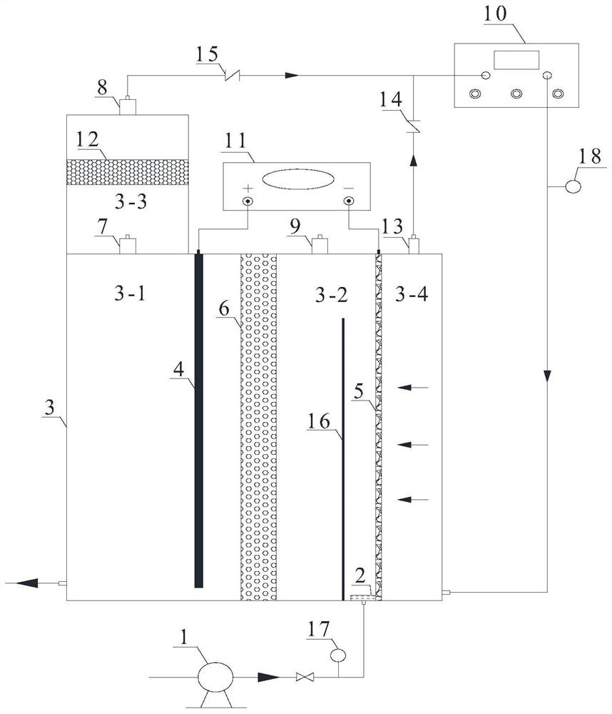
[0042] Equipment for in-situ oxygen generation and ozone enhanced three-stage electrochemical water treatment, see figure 2 , is basically the same as Embodiment 1, except that it also includes a gas pressure valve 13 located at the top of the cathode inlet chamber 3-4, and a No. 1 gas check valve 14 and a No. 2 gas check valve 15. When the intake air flow and pressure are too large, the air pressure valve 13 is opened, so that the gas in the cathode air intake chamber 3-4 is returned to the ozone generator 10 air intake. In this way, on the one hand, it is ensured that the cathode 5 can efficiently complete non-bubble or micro-bubble gas distribution and reaction, improve the utilization rate of ozone, and reduce the pollution of ozone tail gas; The No. 1 gas check valve 14 is located in the middle of the gas outlet of the oxygen storage chamber 3-3 and the air inlet of the ozone generator 10, preventing the gas from flowing back from the pressure valve 13 to the air inlet o...

Embodiment 3

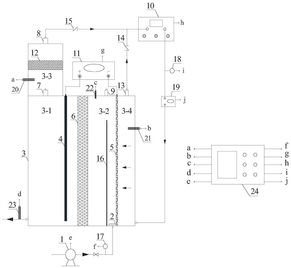
[0045] Equipment for in-situ oxygen generation and ozone enhanced three-stage electrochemical water treatment, see image 3 , is basically the same as Embodiment 2, the difference is only in that it also includes an ozone concentration monitor 19, a No. 1 air pressure sensor 20, a No. 2 air pressure sensor 21, a total oxide concentration monitoring probe 22, a residual oxide concentration monitoring probe 23 and An automatic control unit 24 for controlling each component;

[0046] The ozone concentration monitor 19 is located between the ozone generator 10 and the cathode air inlet chamber 3-4, and is used to monitor the gas phase ozone concentration added; No. 1 air pressure sensor 20 is placed on the side wall of the oxygen storage chamber 3-3 for Monitor the air pressure in the oxygen storage chamber 3-3; No. 2 air pressure sensor 21 is placed on the side wall of the cathode air intake chamber 3-4 for monitoring the air pressure in the cathode air intake chamber 3-4; the to...


PUM


Abstract

The invention provides a three-stage electrochemical water treatment equipment for in-situ oxygen production and ozone enhancement, which includes a water inlet device, a reaction device, an oxygen storage room, and an anode, a cathode, and a water-permeable and gas-insulating catalytic layer arranged inside the reaction device. The cathode and the water-permeable and gas-insulating catalytic layer are all airtightly connected with the inner wall of the reaction device, and the internal space of the reaction device is divided into an anode chamber, a cathode chamber and a cathode air inlet chamber, the anode is located in the anode chamber, and the oxygen storage chamber is located in the anode chamber The top and communicate with it; the gas outlet of the oxygen storage chamber is connected with the air inlet of the cathode inlet chamber through the ozone generator, and the water outlet of the water inlet device is connected with the water inlet of the cathode chamber. The invention also provides a method for treating water by using the device. Through the ingenious structure design and process conception of the reaction device, the present invention not only utilizes the by-product of oxygen evolution at the anode as a gas source prepared by ozone, which saves operating costs, but also reduces harmful by-products through the improvement of the gas distribution method and the reaction flow field. generation and pollution of ozone tail gas.

Description

technical field [0001] The invention belongs to the field of water treatment equipment, and in particular relates to in-situ oxygen generation and ozone-enhanced three-stage electrochemical water treatment equipment and a water treatment method using the same. Background technique [0002] In recent years, environmental pollution has become increasingly serious, especially water pollution, which poses a threat to ecological security and human health. With the continuous revision and improvement of water quality standards, traditional technology and equipment can no longer meet the needs of water treatment, and it is increasingly urgent to develop efficient, economical, and environmentally friendly water treatment equipment and methods. [0003] Advanced oxidation technology is currently a research hotspot in the field of water treatment, and it also has a good treatment effect on refractory wastewater. Electrochemical / ozone coupling is a novel advanced oxidation water treat...

Claims


Application Information

Patent Timeline
Patent Type & Authority Patents(China)
IPC IPC(8): C02F1/461C02F1/72C02F1/78
CPCC02F1/46104C02F1/722C02F1/725C02F1/78C02F2201/782
Inventor 吴东海陆光华周超王泽龙周颖刘建超
Owner HOHAI UNIV
Why Eureka
Try Eureka