Ceramic composite material, manufacturing method thereof, and wavelength converter
A technology of ceramic composite material and ceramic body, which is applied in the direction of instruments, nonlinear optics, optics, etc., can solve the problems of enlarged emitted light spot, lack of excitation light scattering, and reduced light collection efficiency, so as to improve product production efficiency and improve optical efficiency. The effect of improving conversion efficiency and reducing the difficulty of subsequent processing
- Summary
- Abstract
- Description
- Claims
- Application Information
AI Technical Summary
Problems solved by technology
Method used
Image

Examples
preparation example Construction
[0044] In the preparation method of the prior art (such as CN101405368A), generally by changing the sintering temperature, sintering time, cosolvent, the pressure of the atmosphere during sintering to change the pore size and concentration of the luminescent ceramics, or by adding a pore phase forming agent to form stomata. In some prior art, the ceramic composite material containing the solid particles is obtained by sintering the solid particles together with the luminescent ceramic raw materials. However, no matter which method is used, the generated pores or solid particles are roughly uniformly distributed in the ceramic composite material. When it is necessary to polish and coat ceramic composite materials, uneven structures will inevitably be formed on the surface of ceramic composite materials, which greatly affects the quality of film formation.
[0045] Therefore, the present invention proposes to form ion implantation parts in the ceramic body by means of ion impla...
Embodiment 1
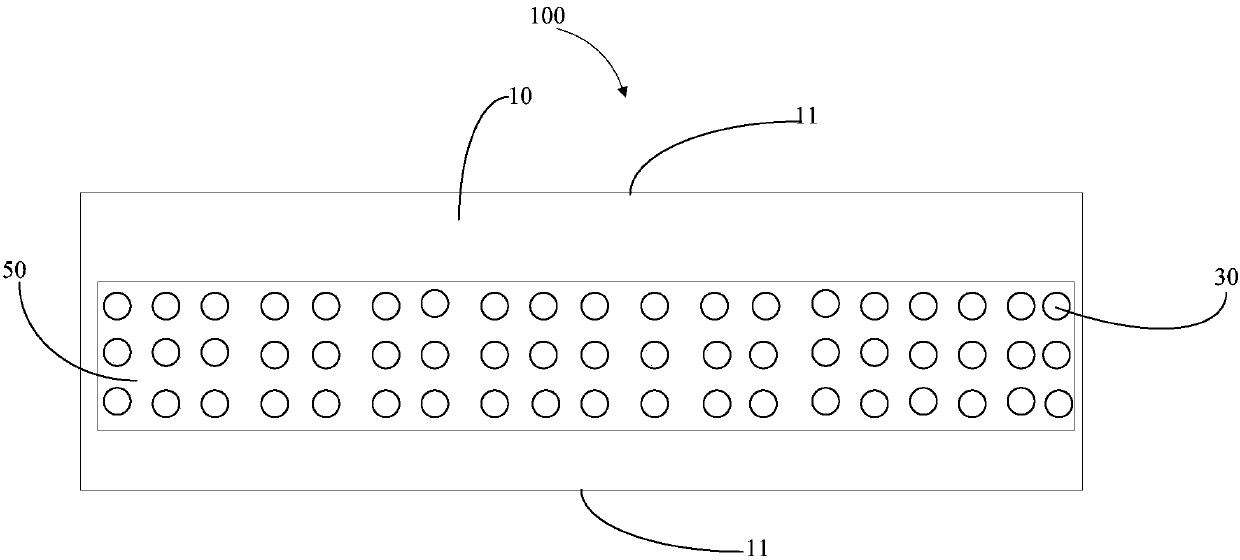
[0061] The ceramic body Ce:Gd obtained by sintering 3 al 5 o 12 Glue to the sample stage of the ion implanter with double-sided carbon conductive adhesive.
[0062] Aluminum and oxygen ions are co-implanted into the ceramic body 10 . In the ion implantation process, the implant dose is 5×10¹⁷ ions / cm 2 , with an injection rate of 1×10 13 ions / cm 2 / s, the ceramic body 10 is heated to 700°C of the ion implanter, with different energies, such as 6.0MeV, 6.1MeV, 6.2MeV, 6.3MeV, 6.4MeV, 6.5MeV, 6.6MeV, 6.7MeV, 6.8MeV, 6.9MeV , 7.0 MeV, ion implantation treatment is performed on the ceramic body 10 in sequence. Put the ion-implanted ceramic body 10 into an annealing furnace, and anneal at 400° C. for 3 hours under vacuum conditions to obtain a translucent ceramic composite material 100. The total volume of the ion-implanted parts 30 accounts for The score is 3%.
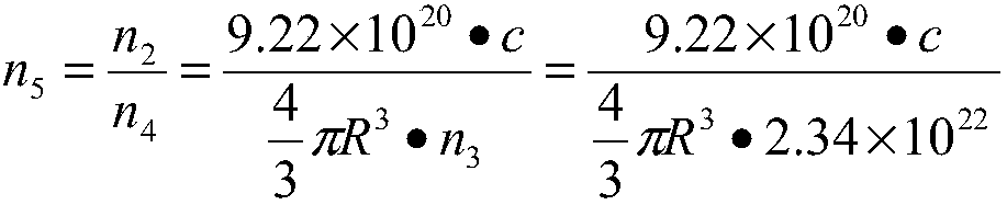
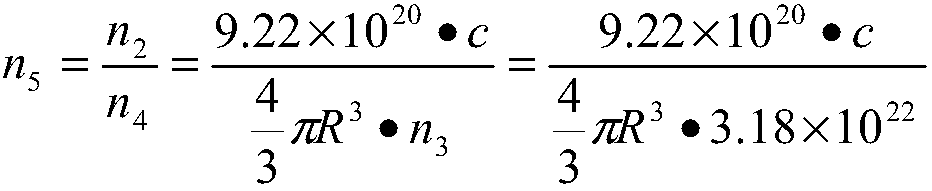
[0063] The calculated concentration of aluminum is 2c%, then the concentration of alumina molecules is c%. The...
Embodiment 2
[0067] The ceramic body Ce:Y obtained by sintering 3 Al 5 o 12 Glue to the sample stage of the ion implanter with double-sided carbon conductive adhesive.
[0068] Titanium and oxygen ions are co-implanted into the ceramic body 10 . In the ion implantation process, the implant dose is 5×10 17 ions / cm 2 , with an injection rate of 1×10 13 ions / cm 2 / s, heat the ceramic body 10 to 800°C with different energies, such as 6.0MeV, 6.1MeV, 6.2MeV, 6.3MeV, 6.4MeV, 6.5MeV, 6.6MeV, 6.7MeV, 6.8MeV, 6.9MeV, 7.0MeV , performing ion implantation treatment on the ceramic body 10 in sequence.
[0069] After the injection is completed, the ceramic body 10 is taken out, and the conductive carbon glue is removed. The average diameter of the ion implanted part 30 after the ion implantation treatment is 10-100 nm. Put the ion-implanted ceramic body 10 into an annealing furnace, and anneal at 1000° C. for 8 hours under vacuum conditions to obtain a translucent ceramic composite material 10...
PUM
| Property | Measurement | Unit |
|---|---|---|
| absorption coefficient | aaaaa | aaaaa |
| diameter | aaaaa | aaaaa |
| density | aaaaa | aaaaa |
Abstract
Description
Claims
Application Information
 - Generate Ideas
- Intellectual Property
- Life Sciences
- Materials
- Tech Scout
- Unparalleled Data Quality
- Higher Quality Content
- 60% Fewer Hallucinations
Browse by: Latest US Patents, China's latest patents, Technical Efficacy Thesaurus, Application Domain, Technology Topic, Popular Technical Reports.
© 2025 PatSnap. All rights reserved.Legal|Privacy policy|Modern Slavery Act Transparency Statement|Sitemap|About US| Contact US: help@patsnap.com