
Laser surface cladding method of boiler water wall tube of thermal power station

A water-cooled wall tube and laser cladding technology, applied in the field of thermal power station boiler water-cooled wall tube, can solve the problems of easy peeling service life, cooling medium damage, heating tube explosion, etc., to avoid high temperature aging, excellent high temperature performance, avoid cracking effect

Inactive Publication Date: 2018-02-23
上海业识科技有限公司
View PDF7 Cites 2 Cited by
  • Summary
  • Abstract
  • Description
  • Claims
  • Application Information

AI Technical Summary

Problems solved by technology

[0005] 2. The erosion and wear of the outer surface of the pipe wall is mainly due to the erosion of coal powder and fly ash, which causes the pipe wall to thin toward the outer surface of the fire side until the pipe bursts;
[0006] 3. The inside of the pipe is blocked, the circulation of the cooling medium is damaged, or the water level is low, resulting in stress fracture damage;
[0007] 4. Long-term heating and bursting caused by high-temperature creep of the material;
[0010] In addition to installing anti-corrosion baffles and strictly controlling the pulverized coal particles entering the furnace, thermal spraying is mainly used to improve the service performance of the water-cooled wall tube surface on the fire side, but the thermal spraying coating and the substrate are not metallurgically bonded, and the service life is easy to peel off Low, in recent years, laser cladding technology is developing rapidly. It can combine various alloy elements and carbide oxides and other multi-components, and the coating produced by laser cladding technology can be metallurgically combined with the substrate, which has obvious development prospects. However, there are still technical bottlenecks that are more sensitive to cracking of the cladding layer to be broken through

Method used


Image

  • Laser surface cladding method of boiler water wall tube of thermal power station
  • Laser surface cladding method of boiler water wall tube of thermal power station
  • Laser surface cladding method of boiler water wall tube of thermal power station

Examples


Embodiment 1

[0032] Embodiment 1: A laser cladding strengthening method for water-cooled wall tubes (T91) of a power plant furnace includes the following steps:

[0033] 1) Preparing the preset paint: the weight ratio of the light-absorbing paint of the preset paint to Ni-based alloy powder is 1:1, and the composition ratio of the selected light-absorbing paint is:

[0034]

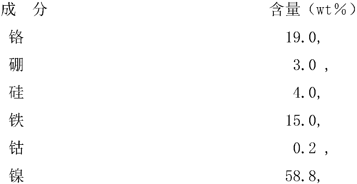
[0035] The composition ratio of described Ni-based multi-element alloy powder is:

[0036]

[0037] Weigh the raw materials according to the selected ratio. The weight percentage of the light-absorbing paint and Ni-based alloy powder in the preset coating is 1:1. After fully dispersing and mixing in a nano-scale wet grinding machine for 3 hours, put the Ni-based multi-element alloy powder into it, and fully disperse and mix for 4 hours to form a coating;

[0038] 2) coating the glue on the surface of the water-cooled wall tube, the thickness of the coating layer is 0.35mm;

[0039] 3) Under the protection of a...

Embodiment 2

[0040] Embodiment 2: adopt carbon dioxide laser processing machine to carry out laser cladding to described water-cooled wall tube (15CrMo), comprise the following steps:

[0041] 1) Prepare preset paint:

[0042] The weight ratio of the light-absorbing paint of the preset paint to the Ni-based alloy powder is 1:1.25, and the composition ratio of the light-absorbing paint is:

[0043]

[0044]

[0045] The composition ratio of described Ni-based multi-element alloy powder is:

[0046]

[0047] Weigh the raw materials according to the selected ratio, the weight percentage of the light-absorbing paint and Ni-based alloy powder in the preset coating is 1:1.25, put the light-absorbing paint into high-speed circulation, large-flow ultra-fine After fully dispersing and mixing in a nano-scale wet grinding machine for 4 hours, put the Ni-based multi-element alloy powder into it, and fully disperse and mix for 3 hours to form a coating;

[0048] 2) Coating the glue coating o...

Embodiment 3

[0050] Embodiment 3: adopting carbon dioxide laser processing machine to carry out laser cladding to described water-cooled wall tube (T91), comprises the following steps:

[0051] 1) Preparation of preset paint: the weight ratio of the light-absorbing paint of the preset paint to Ni-based alloy powder is 1:1.2, and the composition ratio of the selected light-absorbing paint is:

[0052]

[0053]

[0054] The composition ratio of described Ni-based multi-element alloy powder is:

[0055]

[0056] Weigh the raw materials according to the selected ratio. The weight percentage of the light-absorbing paint and Ni-based alloy powder in the preset coating is 1:1.1. After fully dispersing and mixing in a nano-scale wet grinding machine for 4 hours, add the Ni-based multi-element alloy powder, and fully disperse and mix for 4 hours to form a coating;

[0057] 2) Coating the glue coating on the surface of the water-cooled wall tube, the thickness of the coating layer is 0.4mm; ...


PUM

PropertyMeasurementUnit
thicknessaaaaaaaaaa
thicknessaaaaaaaaaa
thicknessaaaaaaaaaa

Abstract

A laser cladding strengthening method for the fire side of the water-cooled wall pipe of a power plant furnace, comprising the following steps: 1) preparing a preset coating: 2) coating the glue on the surface of the water-cooled wall pipe, The thickness of the coating layer is 0.3-0.5 mm; 3) Under the protection of argon, use a carbon dioxide laser processing machine or a semiconductor laser machine for laser cladding. The invention utilizes the high-absorption laser characteristics of nano-titanium oxide and nano-zinc oxide, and greatly improves the cladding effect of equal incident laser power density; the absorbing coating has a nano-cracking anti-cracking effect in the cladding process, which can avoid cracking of the cladding layer ; Ni-based alloy with excellent high-temperature performance is added to avoid high-temperature aging of the structure in the cladding layer. The invention makes a breakthrough in the laser cladding of the water-cooled wall tube.

Description

technical field [0001] The invention relates to a water-cooled wall pipe of a thermal power station boiler, in particular to a laser surface cladding method for the water-cooled wall pipe of a thermal power station boiler. Background technique [0002] The thermal power plant boiler is a key energy equipment related to the national economy and the people's livelihood, and its important component - the water-cooled wall tube is an evaporation heating surface composed of a certain number of tubes connected in parallel. It is mainly used to absorb the radiant heat of high-temperature flame and flue gas in the furnace, turn the water part into saturated steam, and greatly reduce the temperature of the furnace wall, so the structure of the furnace wall is simplified, the weight of the furnace wall is reduced, and the furnace wall and the outlet of the furnace are reduced. To prevent or reduce the furnace slagging. During use, damage to the water-cooled wall tubes has a great imp...

Claims


Application Information

Patent Timeline
Patent Type & Authority Applications(China)
IPC IPC(8): C23C24/10
CPCC23C24/103
Inventor 张光钧马春印
Owner 上海业识科技有限公司
Learn More