Energy-saving lamp time-delay circuit

A technology of time delay circuit and energy-saving lamp, applied in the direction of electric lamp circuit layout, energy-saving control technology, electric light source, etc., can solve the problems of unsatisfactory energy-saving effect, limited contact reserve, low working frequency, etc., and achieve obvious energy-saving effect and cost The effect of low and high input resistance

Inactive Publication Date: 2017-09-26
徐州众仁灯具有限公司
View PDF1 Cites 0 Cited by
  • Summary
  • Abstract
  • Description
  • Claims
  • Application Information

AI Technical Summary

Problems solved by technology

[0002] LED lights are mainly driven and controlled by integrated circuits. After the power is turned on, the bulb lights up. After it is turned off, the relay is used to realize power self-protection and delay energy saving. Due to the limited reserve of contacts and low operating frequency, this kind of mechanical contact is easy to appear. The problem of contact jitter, the energy saving effect is not ideal

Method used


Image

  • Energy-saving lamp time-delay circuit

Examples


Embodiment Construction

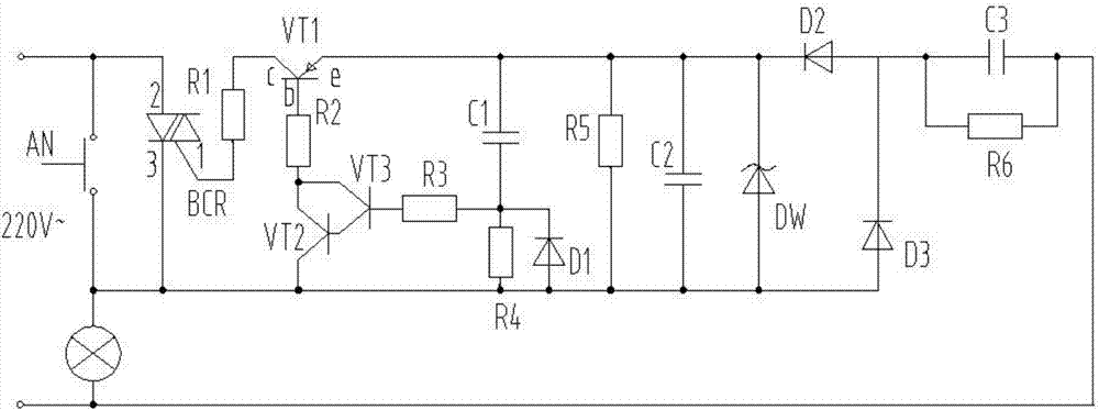
[0015] The present invention will be further described below in conjunction with accompanying drawing.

[0016] like figure 1 As shown, an energy-saving lamp delay circuit, including the button AN and the light bulb ZD in series, the button AN and the light bulb ZD are connected in parallel at two levels of 220V AC voltage, the light bulb ZD and the diode D3 are connected in series, and capacitors are connected in parallel on both sides of the light bulb ZD and the diode D3 C3, a resistor R6 is connected in parallel on both sides of the capacitor C3, the output terminal of the diode D3 is connected to the input terminal of the diode D2, the input terminal of the diode D3 and the output terminal of the diode D2 are connected in parallel with a rectifier diode DW, and the two sides of the rectifier diode DW are connected in parallel A capacitor C2, a series circuit is connected in parallel on both sides of the capacitor C2, a capacitor C1 and a resistor R4 are connected in serie...


PUM


Abstract

The invention discloses an energy-saving lamp time-delay circuit. A 220V alternating current voltage is reduced by a capacitor C3, rectified by a diode D3 and a diode D2, stabilized by a voltage stabilizing tube DW and filtered by a capacitor C2, so as to obtain a direct current voltage; a series circuit is connected in parallel with two sides of the capacitor C2; a capacitor C1 and a resistor R4 are connected in series with the series circuit; two sides of the resistor R4 are connected in parallel with a composite tube electronic switch circuit; the output end of the composite tube electronic switch circuit is connected with a base b of a base transistor VT1; a collector c of the transistor is connected with a pin 1 of a bidirectional silicon-controlled rectifier BCR; a pin 2 and a pin 3 of the bidirectional silicon-controlled rectifier BCR are connected in parallel on two sides of a button AN. The composite tube electronic switch comprises a transistor VT2 and a transistor VT3, so that the input resistance is improved, and the delay amount is ensured; after the bulb goes out, the whole circuit is completely powered off, and the energy-saving effect is obvious; the bidirectional silicon-controlled rectifier serves as a breakpoint switch, only one trigger circuit is needed, the response is extremely fast, non-contact operation is realized, and the energy-saving lamp time-delay circuit is free of spark and noise, high in efficiency and low in cost.

Description

technical field [0001] The invention relates to an energy-saving lamp, in particular to a delay circuit for an energy-saving lamp, and belongs to the technical field of lamps. Background technique [0002] LED lights are mainly driven and controlled by integrated circuits. After the power is turned on, the bulb lights up. After it is turned off, the relay is used to realize power self-protection and delay energy saving. Due to the limited reserve of contacts and low operating frequency, this kind of mechanical contact is easy to appear. The problem of contact jitter, the energy saving effect is not ideal. Contents of the invention [0003] Aiming at the deficiencies of the prior art, a delay circuit for an energy-saving lamp is now provided to ensure that the power is completely cut off after the bulb is extinguished, so as to achieve the effect of optimizing energy saving. [0004] In order to achieve the above purpose, an energy-saving lamp delay circuit includes a seri...

Claims


Application Information

Patent Timeline
Patent Type & Authority Applications(China)
IPC IPC(8): H05B37/02
CPCH05B47/10Y02B20/40
Inventor 于国权
Owner 徐州众仁灯具有限公司
Why Eureka
Try Eureka