
A multi-source low-power low-temperature plasma polymerization coating device and method

A low-temperature plasma and coating device technology, applied in the field of plasma, can solve the problems of poor quality uniformity of batch products, uneven spatial distribution of plasma, and poor quality of polymer coatings, etc., to achieve good product quality uniformity , not easy to excessive damage, good quality effect

Active Publication Date: 2018-03-27
JIANGSU FAVORED NANOTECHNOLOGY CO LTD
View PDF6 Cites 0 Cited by
  • Summary
  • Abstract
  • Description
  • Claims
  • Application Information

AI Technical Summary

Problems solved by technology

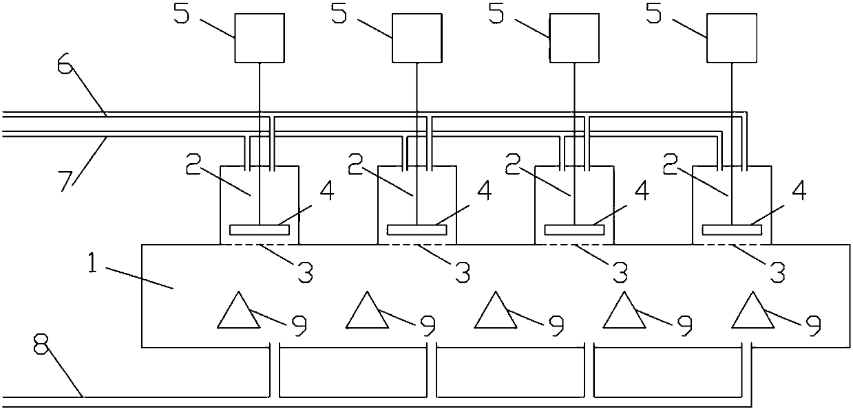
[0004] The purpose of the present invention is to use large-area, high-power high-frequency discharge source for the existing plasma polymerization coating device to produce plasma that is not evenly distributed in space, has poor quality uniformity of batch-processed products, high plasma energy, and low density. High, easy to destroy the chemical monomer structure excessively, so that the quality of the formed polymer coating is poor, and the crosstalk between the high-frequency discharge sources that exist in the combination of multiple small-area, low-power high-frequency discharge sources, Problems such as the uneven spatial distribution of the generated plasma provide a multi-source low-power low-temperature plasma polymerization coating device

Method used


Image

  • A multi-source low-power low-temperature plasma polymerization coating device and method
  • A multi-source low-power low-temperature plasma polymerization coating device and method

Examples


Embodiment 1

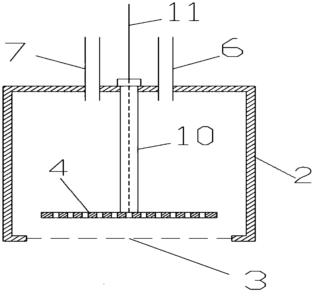
[0027] A multi-source low-power low-temperature plasma polymerization coating device. In the device, multiple discharge chambers are installed on the wall of the main vacuum chamber. The discharge chambers are cylindrical and made of metal. The diameter range is The depth is 150mm; the distance between the axes of adjacent discharge chambers is 70mm; a plane grounding grid is installed at the opening of the discharge chamber leading to the main vacuum chamber; a porous electrode plate is installed near the grid in the discharge chamber, and the porous electrode plate is Evenly distributed through holes, the diameter of the through holes is 1mm, and the hole spacing is 1mm; the porous electrode plate is parallel to the grid and the gap is less than 8mm; the porous electrode plate is fixed by an insulating bracket, connected to a low-power high-frequency power supply through a wire, and the power of the low-power high-frequency power supply The power is 5W, the frequency is 20kH...

Embodiment 2

[0029] A method for coating using the multi-source low-power low-temperature plasma polymerization coating device described in Embodiment 1, is characterized in that: mainly comprising the following steps:

[0030] (1) Place the substrate to be processed in the vacuum chamber, turn on the vacuum pump to pump the vacuum chamber to 1Pa;

[0031] (2), pass into carrier gas, make carrier gas enter discharge cavity and vacuum chamber through carrier gas pipeline, described carrier gas is argon, maintain the vacuum degree in vacuum chamber to be 30Pa; Pass into monomer vapor, make single The monomer vapor enters the vacuum chamber through the monomer vapor pipeline. The monomer vapor contains at least one unsaturated carbon-carbon bond, and one of the unsaturated carbon atoms does not contain a substituent. The structure of the monomer may contain a halogen functional group or Other functional groups, the halogen functional group is one or more of F, Cl, Br, I, and other functional ...

Embodiment 3

[0034] A multi-source low-power low-temperature plasma polymerization coating device. In the device, multiple discharge chambers are installed on the wall of the main vacuum chamber. The discharge chambers are cylindrical and made of metal. The diameter range is The depth is 30mm; the distance between the axes of adjacent discharge chambers is 400mm; a flat ground grid is installed at the opening of the discharge chamber leading to the main vacuum chamber; a porous electrode plate is installed near the grid in the discharge chamber, and the porous electrode plate is Evenly distributed through holes, the diameter of the through holes is 10mm, and the hole spacing is 10mm; the porous electrode plate is parallel to the grid and the gap is less than 8mm; the porous electrode plate is fixed by an insulating bracket, connected to a low-power high-frequency power supply through a wire, and the power of the low-power high-frequency power supply The power is 100W, and the frequency is ...


PUM


Abstract

A multi-source low-power low-temperature plasma polymerization coating device and method belong to the field of plasma technology. In this device, multiple discharge chambers are installed on the wall of the main vacuum chamber, and a plane ground grid and a porous electrode plate are installed in each discharge chamber. The porous electrode plate is parallel to the grid and maintains a gap, and is connected to a low-power high-frequency power supply. ; The carrier gas pipeline and the monomer steam pipeline are respectively connected to each discharge chamber, the substrate to be treated is placed inside the main vacuum chamber, the vacuum pump is turned on, the carrier gas and monomer steam are introduced, and the porous electrode plate faces the discharge chamber. Wall discharge, the monomer vapor is polymerized, and the polymerized product passes through the small holes on the porous electrode plate and the grid into the vacuum chamber and is deposited on the surface of the substrate to form a polymer coating. The device of the invention has the advantages of uniform plasma spatial distribution, good quality uniformity of batch-processed products, low plasma energy and density, low chemical monomer structure, and good quality of formed polymer coating.

Description

technical field [0001] The invention belongs to the field of plasma technology, in particular to a low-temperature plasma polymerization coating device and method. Background technique [0002] As an effective method to improve the surface properties of materials, plasma surface treatment is widely used in aerospace, automobile manufacturing, machinery heavy industry and hardware tool manufacturing and other fields. Plasma polymerized coating is an important surface treatment method. In the process of plasma polymerization coating, process gas and gaseous organic monomers need to be introduced into the vacuum chamber, and the organic gaseous monomers are plasmaized by discharge to produce various active species. Occasionally, an addition reaction occurs between the active species and the monomer to form a polymer. Because the polymer coating is generally non-conductive, it is usually necessary to use a high-frequency discharge source to generate plasma, and in order to imp...

Claims


Application Information

Patent Timeline
Patent Type & Authority Patents(China)
IPC IPC(8): B05B5/10B05B5/08
CPCB05B5/08B05B5/10H01J37/32449H01J37/32834H01J37/32568H01J37/32541
Inventor 宗坚
Owner JIANGSU FAVORED NANOTECHNOLOGY CO LTD
Learn More