
Delay line capable of automatically balancing technological deviations and temperature influences

A technology of process deviation and automatic balance, applied in the direction of automatic power control, pulse processing, electrical components, etc., can solve the problems of delay-locked loop unable to lock, small dynamic range of operating frequency, large deviation of output signal, etc., to save chips Area and cost, improved frequency dynamic range, reduced latency effects

Inactive Publication Date: 2016-08-17
深圳市芯卓微科技有限公司
View PDF8 Cites 5 Cited by
  • Summary
  • Abstract
  • Description
  • Claims
  • Application Information

AI Technical Summary

Problems solved by technology

The structure of the simple delay unit is the NOT gate structure in the digital circuit. This kind of control is simple and can be realized by digital programming. The disadvantage is that the delay time is a discrete value, and the minimum delay is the delay of a NOT gate. The dynamic range of the operating frequency is small. The deviation of the output signal is large
The other is the delay unit with a charge pump structure. This structure has better linearity than the delay unit with a non-gate structure. However, due to the deviation of the chip manufacturing process and the influence of temperature, the delay unit charges and discharges the capacitor at an inconsistent time, and the output signal of the delay unit The high and low level duty cycle will be inconsistent. After the cumulative effect of multi-stage delay units, it will lead to poor phase interval consistency of the delay line output signal, narrow frequency working range, and may even cause the delay locked loop to fail to lock.

Method used


Image

  • Delay line capable of automatically balancing technological deviations and temperature influences
  • Delay line capable of automatically balancing technological deviations and temperature influences
  • Delay line capable of automatically balancing technological deviations and temperature influences

Examples


Embodiment Construction

[0021] The specific implementation of a delay line that automatically balances process deviation and temperature effects in the DLL disclosed in the present invention will be described in detail below with reference to the accompanying drawings, which is not intended to limit the scope of the present invention.

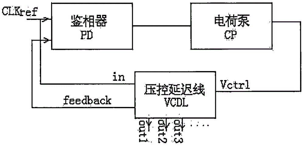
[0022] figure 1 The structure diagram of the delay locked loop is shown, which is composed of three parts: a phase detector PD, a charge pump CP, and a voltage-controlled delay line VCDL. The phase detector CLKref signal is the input reference clock signal, and the output signal feedback of the delay line VCDL is the output signal of the last stage on the delay line, which is sent to the phase detector to compare with the phase of the CLKref signal, and the obtained phase difference is sent to the charge pump, the charge pump outputs a VCTRL voltage control signal according to the phase difference information, and this voltage control signal is used to control the del...


PUM


Abstract

The present invention is a delay line for automatically balancing process deviation and temperature influence, the delay line is connected in series by a plurality of delay units, each of the delay units includes a delay circuit and an inversion circuit; transistors P1, P2, P3, P4 is a PMOS transistor of the same size, and transistors N1, N2, N3, and N4 are NMOS transistors of the same size; the transistors P1, P3, N1, and N3 form one of the delay circuits; the transistors P2, P4, N2, and N4 One of the reverse circuits is formed. The delay line designed by the method of the present invention can automatically adjust the high and low level duty ratio of the delay unit, so that the high and low level duty ratio of the signal is approximately 1 / 2; the delay line designed by the present invention can effectively increase the frequency of the input signal The dynamic range can reduce the locking time of the delay-locked loop; the delay line designed by the invention has a simple structure and adopts standard CMOS electronic devices, which can effectively save chip area and cost.

Description

technical field [0001] The patent of the invention belongs to the field of integrated circuit chips, and in particular relates to a voltage-controlled delay circuit of a delay-locked loop of a chip. Background technique [0002] Delay-locked loops are widely used because of the advantages that phase-locked loops do not have. The biggest advantage of delay-locked loops is that it is easy to achieve precise delay of a certain waveform. There are many practical applications based on this advantage. For example, to shift the phase of a signal by 120 degrees, a three-stage delay unit can be used to delay the delay. The entire delay line is delayed by one cycle, and the output of the first-stage delay unit is the desired signal. For example, to obtain 6 clocks with equal phase intervals, a delay line with 6 stages of delay units can be adopted, and each stage of delay units is delayed by 60 degrees. The delay line is the key and difficult point in the design of the delay locked ...

Claims


Application Information

Patent Timeline
IPC IPC(8): H03L7/10H03L7/085H03K5/00
CPCH03L7/10H03K5/00H03K2005/00123H03K2005/00143H03K2005/00195H03L7/085
Inventor 肖本钟国华罗四阳
Owner 深圳市芯卓微科技有限公司
Learn More