Grinder and grinding machine

A technology of grinding discs and grinding machines, which is applied to grinding machine tools, grinding devices, grinding tools, etc., can solve the problems of high wear degree and large amount of movement, and achieve the effect of grinding uniformity.

Active Publication Date: 2015-10-14
MILANO SEISAKUSYO
View PDF5 Cites 7 Cited by
  • Summary
  • Abstract
  • Description
  • Claims
  • Application Information

AI Technical Summary

Problems solved by technology

However, the peripheral speed is different between the outer and inner peripheral sides of the turntable, so the amount of movement per one rotation of the disk is greater on the outer peripheral side
Therefore, there is a problem that the grinding head on the outer peripheral side is more worn than the grinding head on the inner peripheral side, so that the grinding head on the outer peripheral side does not come into contact with the object.

Method used


Image

  • Grinder and grinding machine
  • Grinder and grinding machine
  • Grinder and grinding machine

Examples


Embodiment 1

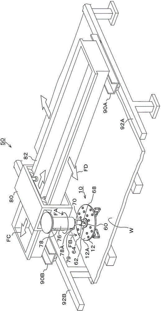
[0025] First, refer to Figure 1 ~ Figure 3 Example 1 of the present invention will be described. figure 1 It is an external perspective view showing the overall structure of the grinder of this embodiment. Such as figure 1 As shown, the grinder 50 of this embodiment is used to grind the surface of an object W such as a stone, and this embodiment is an example of a uniaxial type. The grinder 50 is equipped with a grinding disc 10 at the top of the rotating shaft 70 of the main shaft 76, and the grinding disc 10 can be as figure 1 Rotate as indicated by arrow FA in . In addition, a hydraulic cylinder 78 is provided on the side of the spindle 76 as a pressing member for pressing the rotating shaft 70 toward the object W (see arrow FB). A rod 78A of the hydraulic cylinder 78 is connected to the rotary shaft 70 via a connection member 79 . In addition, the spindle 76 is a self-propelled type capable of moving along the surface of the object W. As shown in FIG.

[0026] Fo...


PUM


Abstract

A grinder includes a rotatable disk to be pressed to a workpiece; a plurality of grinding bodies provided on one principal surface of the disk so as to cross a circumferential direction of the disk, each having a grinding stone chip on a side contacting the workpiece; and support devices, each supporting each of the grinding bodies so that the grinding stone chip swings with respect to the principal surface. Each support device supports each grinding body at a position at which an abrasion amount of the grinding stone chip is made uniform when the disk is rotated while being pressed to the workpiece so that a pressure to be applied to the grinding stone chip on an outer peripheral side of the disk becomes smaller than a pressure to be applied to the grinding stone chip on an inner peripheral side of the disk.

Description

technical field [0001] The present invention relates to a grinding disc and a grinding machine, and more specifically, to uniformization of grinding when a grinding head (Japanese: whetstone chip) wears and uniformization of the amount of wear of the grinding head. Background technique [0002] When grinding a stone, the surface of the stone to be polished is not completely flat, but strictly speaking has inclinations, undulations, and curvatures. The grinding machine has a structure in which the grinding plate with the grinding head can be tilted relative to the grinding object, so even if the stone surface is tilted, etc., the grinding operation can be performed well. However, since the peripheral speed is different between the outer peripheral side and the inner peripheral side of the turntable, the movement amount per one rotation of the disk is larger on the outer peripheral side. Therefore, there is a problem that the grinding head on the outer peripheral side is more...

Claims


Application Information

Patent Timeline
IPC IPC(8): B24B37/10B24B37/12
CPCB24B7/224B24B37/10B24B37/12
Inventor 大给慎吾
Owner MILANO SEISAKUSYO
Why Eureka
Try Eureka