
Device reducing light degradation of solar cell and method thereof

A solar cell and light-induced attenuation technology, applied in circuits, photovoltaic power generation, electrical components, etc., can solve the problems of low output, high power consumption, and insufficient effect, and achieve low cost, low power consumption, and obvious effect. Effect

Active Publication Date: 2015-04-08
HENGDIAN GRP DMEGC MAGNETICS CO LTD
View PDF5 Cites 20 Cited by
  • Summary
  • Abstract
  • Description
  • Claims
  • Application Information

AI Technical Summary

Problems solved by technology

The disadvantage of this utility model is that the effect of the device is not obvious enough, the power consumption is high, and the output is not high.

Method used


Image

  • Device reducing light degradation of solar cell and method thereof
  • Device reducing light degradation of solar cell and method thereof
  • Device reducing light degradation of solar cell and method thereof

Examples


Embodiment 1

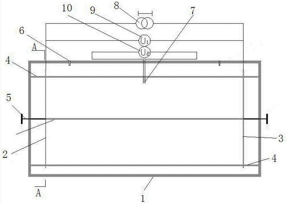
[0041] Implementation Example 1: 100 sheets of monocrystalline solar cells with a conversion efficiency of 19.0% and a side length of 156 mm (the cell area is 238.95 cm 2 ), put it in the constant temperature box, fix the left conductive plate and the right conductive plate, connect the circuit, and cover the upper cover of the constant temperature box; Start access to N 2 ; After the preheating is completed, turn on the power supply and pass a positive DC current to the cell, with a current density of 3mA / cm 2 , and at the same time set the temperature of the incubator at 125°C for treatment, keep the N 2 ;Observe the changes of the first voltmeter and the second voltmeter, record the change value of the second voltmeter with time, until the second voltmeter is stable; wait for the battery slice to cool down, take out the battery slice to test its electrical performance, and compare the electric current before treatment. Performance and efficiency: package the processed sol...

Embodiment 2

[0042] Implementation example 2: according to the method described in implementation example 1, 100 sheets of monocrystalline solar cells with a conversion efficiency of 19.2% and a side length of 156mm (the cell area is 238.95cm 2 ) were processed in the same way, and the treated solar cells were packaged in modules, and a group of untreated solar cells with the same conversion efficiency gear were also selected for module packaging. As a control, the two modules were exposed to sunlight Downlight 60KWh / m 2 , to test the light-induced attenuation of the components; comparative analysis, the treated solar cells, the light attenuation of the component power is within 1%, while the power attenuation of the control component reaches 3.5%.

Embodiment 3

[0043] Implementation example 3: Considering the influence of the current factor passed in during the processing of the cell on the processing result, on the basis of implementation example 1, change the current density passed in to 2mA / cm 2 and 20mA / cm 2 Divide into two groups, and other conditions remain unchanged. Each group selects 100 monocrystalline cells with a conversion efficiency of 19.0% and a side length of 156 mm for the experiment. During the battery processing process, the first and second voltmeters are analyzed. Changes; also test the electrical performance and efficiency of the battery after processing, and package the components, 60KWh / m 2 Sunlight, and compare the results of light attenuation. It is basically consistent with the result in Example 1.


PUM


Abstract

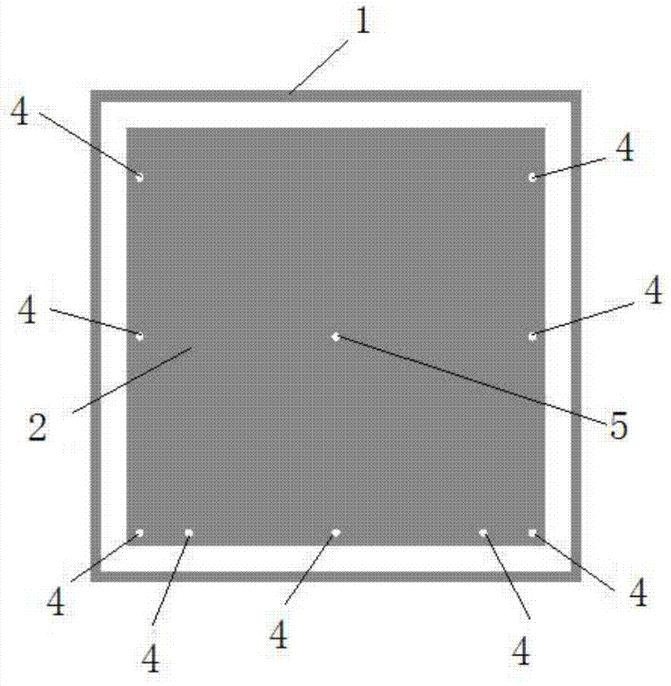
The invention discloses a device reducing light degradation of a solar cell and a method thereof. The device is simple in structure and is easy to product in volume. The device comprises a thermostat, a left conducting plate, a right conducting plate, and a plurality of insulating support rods. The insulating support rods are installed in the thermostat. Two ends of the insulating support rod are respectively disposed on the left side surface and the right side surface of the thermostat. The left conducting plate and the right conducting plate are disposed in the thermostat and are installed on the insulating support rods. A constant current DC power supply is connected between the left conducting plate and the right conducting plate. A first voltmeter is connected with the left conducting plate and the right conducting plate. The middle of the internal of the thermostat is also provided with two pieces of sheet metal. A second voltmeter is connected between the two pieces of sheet metal. Beneficial effects of the device are that production technology of a production line is not changed, devices and equipment which are very expensive and occupy large land are not needed, original electrical performance and efficiency of a cell piece are not changed, the device is simple in structure, easy in mass production, obvious in effect, little in power consumption, high in yield, and high in reliability.

Description

technical field [0001] The invention relates to the field of photovoltaic technology, in particular to a device and method for reducing light-induced attenuation of solar cells. Background technique [0002] As an alternative to traditional energy generation technology, "photovoltaic" is considered to be one of the most promising new energy industries. In recent years, the photovoltaic industry based on crystalline silicon solar cells has developed on a large scale, and photovoltaic products have been used in various places and industries. However, with the development of the industry and the increase in demand, many problems have been plaguing people in the industry during the production of photovoltaic products. For example, the light-induced attenuation phenomenon of solar cells and components has not been well resolved in industrial production. Boron-doped crystalline silicon solar cells are currently mainstream products. Silicon wafers are mainly produced using the tr...

Claims


Application Information

Patent Timeline
Patent Type & Authority Applications(China)
IPC IPC(8): H01L31/18
CPCH01L31/1864H01L31/1876Y02E10/50Y02P70/50
Inventor 陈金灯陈健生董方
Owner HENGDIAN GRP DMEGC MAGNETICS CO LTD
Learn More