Electric injection annealing device

An annealing device, a technology of current injection, applied in circuits, electrical components, sustainable manufacturing/processing, etc., to achieve the effect of improving conversion efficiency, high processing efficiency, and high-efficiency annealing effect

Pending Publication Date: 2018-09-07
SUZHOU KZONE EQUIP TECH
View PDF0 Cites 0 Cited by
  • Summary
  • Abstract
  • Description
  • Claims
  • Application Information

AI Technical Summary

Problems solved by technology

[0003] In response to the above defects, annealing treatment is mostly used now, but it is found that if the silicon wafer is kept in an electrified state during the annealing process, the annealing effect of the silicon wafer can be better, and it has more superior performance, but there is no silicon wafer annealing equipment currently Therefore, a reliable working silicon wafer annealing equipment is urgently needed to solve this problem.

Method used


Image

  • Electric injection annealing device
  • Electric injection annealing device
  • Electric injection annealing device

Examples


Embodiment Construction

[0036] The technical solutions of the present invention will be clearly and completely described below in conjunction with the accompanying drawings. Apparently, the described embodiments are some of the embodiments of the present invention, but not all of them. Based on the embodiments of the present invention, all other embodiments obtained by persons of ordinary skill in the art without making creative efforts belong to the protection scope of the present invention.

[0037] In the description of the present invention, it should be noted that the terms "center", "upper", "lower", "left", "right", "vertical", "horizontal", "inner", "outer" etc. The indicated orientation or positional relationship is based on the orientation or positional relationship shown in the drawings, and is only for the convenience of describing the present invention and simplifying the description, rather than indicating or implying that the referred device or element must have a specific orientation, ...


PUM


Abstract

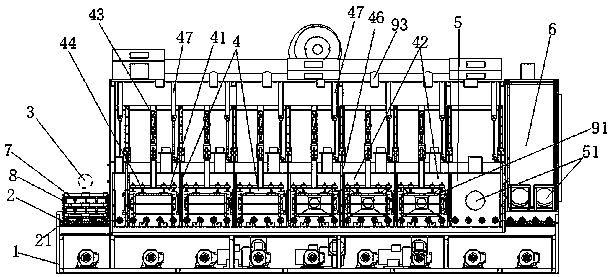
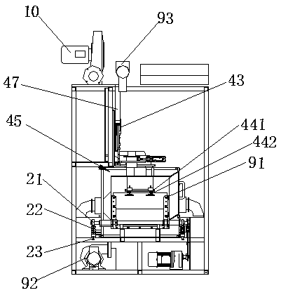
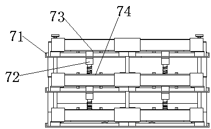
The invention relates to an electric injection annealing device, applied to annealing of a battery piece. The electric injection annealing device comprises a frame main body, wherein a roller conveying system is arranged at the bottom of the frame main body, and a carrier for carrying the battery piece sequentially passes through a feeding station, a reverse current injection station, a cooling station and a blanking station through the conveying roller system to perform annealing treatment; the reverse current injection station is used for performing electric injection on the battery piece inthe carrier, at least two process chambers are arranged in the reverse current injection station, including at least one high-temperature process chamber and at least one low-temperature process chamber, and a heat control system is arranged in the reverse current injection station and is used for adjusting the chamber temperature of the at least one high-temperature process chamber and the at least one low-temperature process chamber. According to the scheme of the invention, the annealing of the battery piece under the condition of electric injection can be realized, the high processing efficiency can be achieved, and the conversion efficiency of the battery piece can be effectively improved.

Description

technical field [0001] The invention relates to the technical field of cell sheet processing, in particular to a device for annealing a cell sheet, in particular to an electric injection annealing device. Background technique [0002] The silicon wafer (battery) contains oxygen, which has the function of absorbing impurities. Annealing the silicon wafer can promote the outward diffusion of oxygen remaining in the silicon, forming a low-oxygen environment (clean area) on the surface of the silicon wafer, thereby Reducing or even eliminating crystal defects caused by oxygen is beneficial to later device manufacturing, and annealing of silicon wafers can affect its resistivity and minority carrier lifetime. In addition, light-induced degradation (LID) refers to the power attenuation phenomenon caused by solar cells and components during the illumination process. In order to improve battery efficiency, PERC (passivated emitter and back local contact cell) high-efficiency batter...

Claims


Application Information

Patent Timeline
Patent Type & Authority Applications(China)
IPC IPC(8): H01L31/18
CPCH01L31/1864Y02P70/50
Inventor 蒋新刘涛陈国才刘斌窦福存
Owner SUZHOU KZONE EQUIP TECH
Why Eureka
Try Eureka