
Direct carbon electrochemical cell

一种电化学、电池的技术,应用在电化学电池领域,能够解决阳极反应复杂等问题

Active Publication Date: 2014-08-27
UNIV COURT OF THE UNIV OF ST ANDREWS
View PDF4 Cites 7 Cited by
  • Summary
  • Abstract
  • Description
  • Claims
  • Application Information

AI Technical Summary

Problems solved by technology

[0011] However, the actual anode reaction may be more complex

Method used


Image

  • Direct carbon electrochemical cell
  • Direct carbon electrochemical cell
  • Direct carbon electrochemical cell

Examples


Embodiment Construction

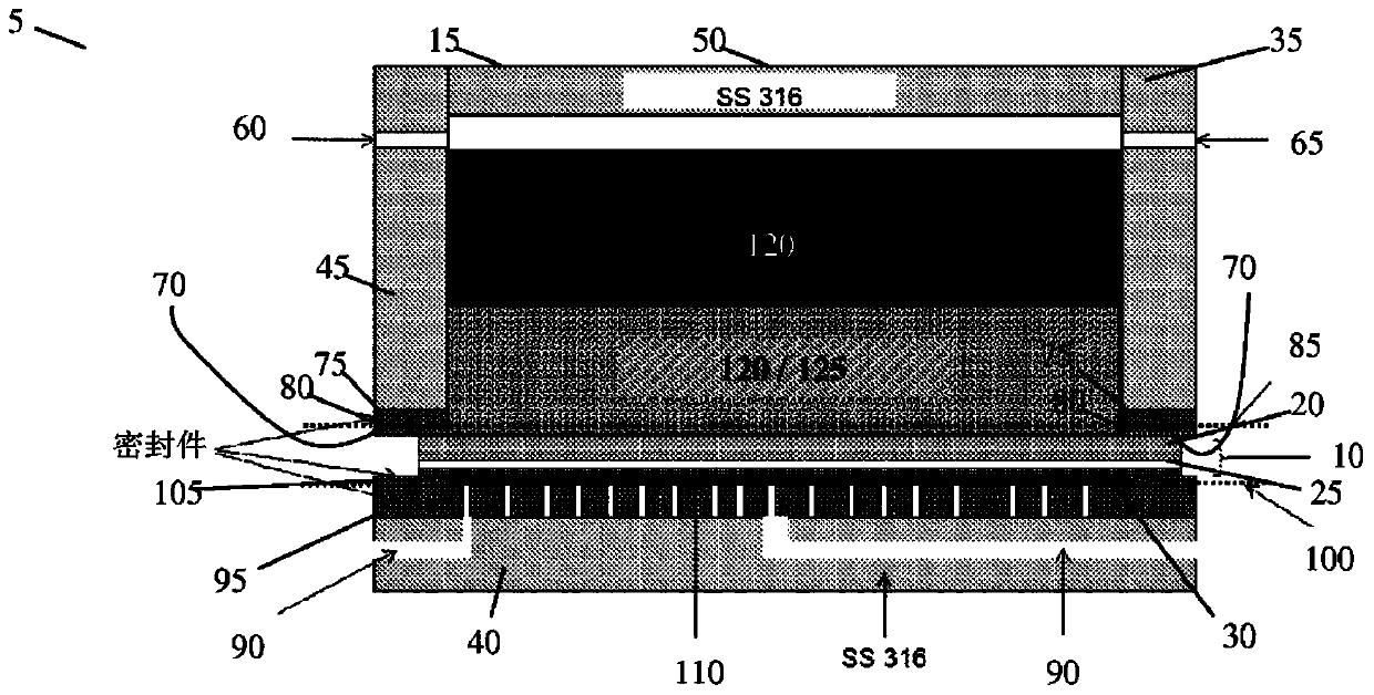
[0097] figure 1 Shown is a cross section of the direct carbon fuel cell system 5 . The system 5 includes a solid oxide electrochemical cell 10 provided within a cell housing 15 . The electrochemical cell 10 includes a solid oxide anode 20 , an ion-conducting solid oxide electrolyte 25 and a solid oxide cathode 30 .

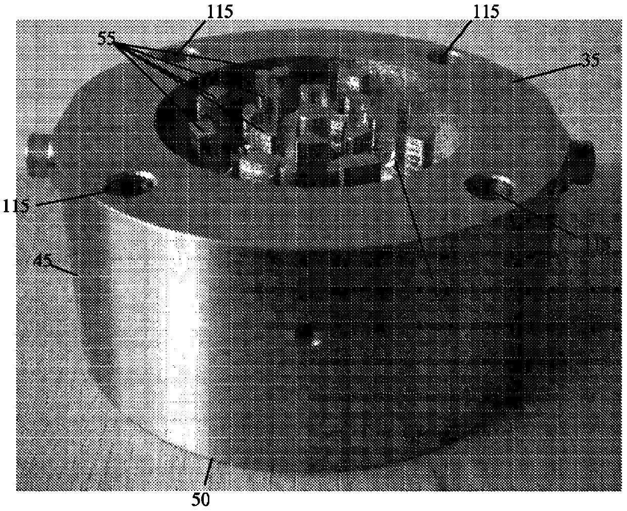
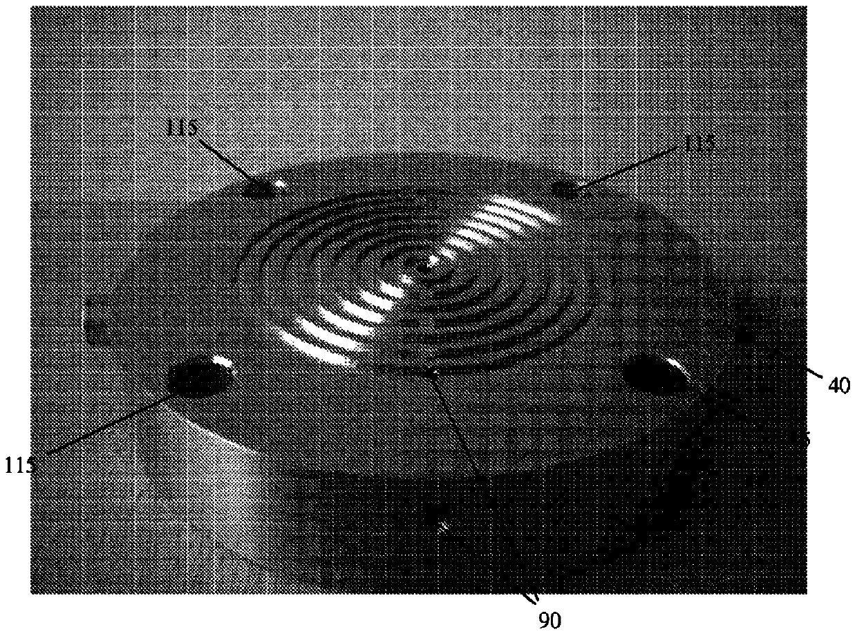
[0098] The housing 15 includes two distinct parts 35, 40, such as figure 2 and 3 As shown, anode casing 35 and cathode casing 40 are compressed and sealed together to sandwich cell 10 with anode 20 of cell 10 facing anode casing 35 and cathode 30 of cell 10 facing cathode casing 40 . In use, the cell 10 is arranged such that the anode casing 35 forms the upper end or top of the system 5 and the cathode casing 40 forms the lower end or bottom of the system 5 . The anode casing 35 is larger than the cathode casing and is configured to carry a mixture of fuel, catalyst and a second electrolyte (molten at operating temperature).

[0099] Anode side current colle...


PUM

PropertyMeasurementUnit
surface areaaaaaaaaaaa

Abstract

A direct carbon fuel cell DCFC system (5), the system comprising an electrochemical cell, the electrochemical cell (10) comprising a cathode (30), a solid state first electrolyte (25) and an anode (20), wherein, the system further comprises an anode chamber containing a second electrolyte (125) and a fuel (120). The system, when using molten carbonate as second electrolyte, is preferably purged with CO2 via purge gas inlet (60).

Description

technical field [0001] The present invention relates to an electrochemical cell, such as a fuel cell. In particular, but not exclusively, the present invention relates to direct carbon fuel cells. Background technique [0002] Carbon fuels have historically been used to generate electricity and extensive and abundant carbon stocks exist. Examples of carbon fuels include biofuels (eg, wood, coconut husks), coal, petroleum coke (residues from refinery distillation processes), pyrolysis carbon, and materials from municipal waste. [0003] Fuel cells operating on solid fuels can provide higher energy densities than fuel cells operating on gaseous fuels. For example, solid carbon contains a higher energy density per unit volume (eg 20.0 kWh / L) than gaseous and liquid fuels such as methanol (4.2 kWh / L), hydrogen (2.4 kWh / L) or diesel (9.8 kWh / L). [0004] In view of the above, direct carbon fuel cells, in which carbon is directly converted into electricity, show great potential...

Claims


Application Information

Patent Timeline
Patent Type & Authority Applications(China)
IPC IPC(8): H01M12/04H01M8/14H01M8/22H01M8/02H01M8/12H01M8/24H01M2/02H01M2/08
CPCH01M8/225H01M8/143H01M8/1233H01M8/2475Y02E60/525H01M8/144H01M8/248Y02E60/521H01M2008/147H01M8/145H01M8/146H01M12/04H01M8/0282H01M8/1009Y02E60/526H01M2/08H01M2/0265Y02E60/50Y02E60/10H01M8/10
Inventor J·T·S·欧文G·蔻尔姜彩荣
Owner UNIV COURT OF THE UNIV OF ST ANDREWS
Learn More