
Carpentry cutter body manufacturing process

A manufacturing process and tool body technology, applied in the field of woodworking tool body manufacturing process, can solve the problems of processing efficiency and surface finish limitations, high manufacturing cost, high material cost, saving machine tool equipment and processing time, and saving metal raw materials , the effect of high dimensional accuracy

Active Publication Date: 2014-01-29
付绍森
View PDF5 Cites 13 Cited by
  • Summary
  • Abstract
  • Description
  • Claims
  • Application Information

AI Technical Summary

Problems solved by technology

[0003] 1. High manufacturing cost
Since high-speed steel, cemented carbide and superhard materials are made of W, Cr, Co or PCD (synthetic polycrystalline diamond), PCBN (polycrystalline cubic boron nitride), although the manufacturing cost of high-speed steel is lower than other materials, it is difficult to process The application of high-strength woodworking composite materials is limited due to the influence of processing efficiency and surface finish; although cemented carbide, PCD, and PCBN materials can meet the processing requirements of high-strength woodworking composite materials, their manufacturing process and formula determine the material cost. high
[0004] 2. There is a contradiction between wear resistance (hardness) and toughness (strength) in the selection of tool materials
[0005] 3. Poor corrosion resistance
But for a long time, although traditional tool materials have high hardness, they are brittle and poor in toughness, and their application is limited to a certain extent.

Method used


Image

  • Carpentry cutter body manufacturing process

Examples


Embodiment Construction

[0058] The specific embodiments of the present invention will be described in further detail below in conjunction with the accompanying drawings.

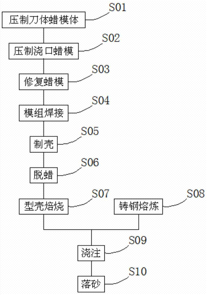
[0059] The invention provides a manufacturing process for a woodworking tool cutter body, the process comprising the following steps:

[0060] S01: Press the wax model of the knife body;

[0061] Take out the wax cylinder from the heat preservation tank, install the wax cylinder on the double-station hydraulic wax mold injection machine, remove the air and hard wax in the wax cylinder before pressing; The hydraulic wax mold injection machine is positioned, the wax mold of the knife body is aligned with the wax injection nozzle of the double station hydraulic wax mold injection machine, and the core of the wax mold of the knife body is in the center of the wax mold of the knife body ;

[0062] Before the double-station hydraulic wax mold injection machine works, a layer of parting agent is sprayed inside the wax mold of the cutter...


PUM


Abstract

The invention relates to a carpentry cutter body manufacturing process comprises the steps of cutter body wax mold body pressing, gate wax mold pressing, wax mold repairing, module welding, shell manufacturing, de-waxing, mold shell roasting, cast steel smelting, casting, and shakeout. The carpentry cutter body manufacturing process provided by the invention has the advantages that: with the carpentry cutter body manufacturing process, carpentry cutter body with high hardness, high toughness, high-temperature resistance, and high cutter body casting size precision can be manufactured. Also, large amount of machine tool equipment and processing time can be saved, and also metal raw materials can be greatly saved.

Description

technical field [0001] The invention relates to the field of mechanical cutter manufacturing, in particular to a manufacturing process of a woodworking cutter body. Background technique [0002] Usually woodworking tool materials mainly include carbon tool steel, alloy tool steel, Stellite alloy, high-speed steel, etc. These materials are often used in occasions with low cutting speed, low feed speed and low processing accuracy requirements, and are generally used for solid wood processing. . But existing woodworking cutter has following shortcoming: [0003] 1. The manufacturing cost is relatively high. Since high-speed steel, cemented carbide and superhard materials are made of W, Cr, Co or PCD (synthetic polycrystalline diamond), PCBN (polycrystalline cubic boron nitride), although the manufacturing cost of high-speed steel is lower than other materials, it is difficult to process The application of high-strength woodworking composite materials is limited due to the in...

Claims


Application Information

Patent Timeline
IPC IPC(8): B22C7/02B22C9/04B22C9/22
Inventor 付绍森
Owner 付绍森
Learn More