
Magnetic separation device and method for reducing hematite-containing material by utilizing microwave

A magnetic separation device and technology for iron minerals, applied in chemical instruments and methods, magnetic separation, solid separation, etc., can solve the problems of equipment structure and related technologies failing to pass the standard, poor reduction and roasting quality, and large dust content in exhaust gas. Achieve the effect of shortening the reaction time, improving the magnetic separation efficiency, and large processing capacity

Active Publication Date: 2013-12-18
INNER MONGOLIA UNIV OF SCI & TECH
View PDF6 Cites 11 Cited by
  • Summary
  • Abstract
  • Description
  • Claims
  • Application Information

AI Technical Summary

Problems solved by technology

The equipment for realizing the above method mainly includes shaft furnaces, rotary kilns and fluidized fluidized furnaces, etc., but these equipments have disadvantages such as low heat transfer coefficient and long reduction time, resulting in unqualified equipment structure and related technologies, not only poor reduction and roasting quality, but also Large, complex structure, high energy consumption, low processing capacity, large dust content in exhaust gas, complex dust collection system, and large investment

Method used


Image

  • Magnetic separation device and method for reducing hematite-containing material by utilizing microwave
  • Magnetic separation device and method for reducing hematite-containing material by utilizing microwave
  • Magnetic separation device and method for reducing hematite-containing material by utilizing microwave

Examples


Embodiment 1

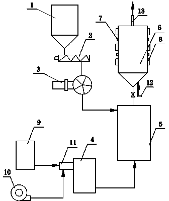
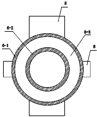
[0034] Embodiment one: see Figure 1-Figure 3 , a magnetic separation device for microwave reduction of materials containing hematite, including a silo 1, a screw feeder 2, a star feeder 3, a preheating reaction furnace 5 and a microwave magnetic separator 6; the upper part of the microwave magnetic separator 6 , and the bottom are respectively provided with a discharge port 13 and a discharge port 12; the bottom of the preheating reaction furnace 5 communicates with the combustion chamber 4, and the gas in the gas storage tank 9 is mixed with the air blown in by the blower 10 and burns through the burner 11 The chamber 4 is combusted, and the CO high-temperature gas produced after combustion enters from the bottom of the preheating reaction furnace 5 .

[0035]Microwave magnetic separator 6 includes: reactor shell 6-1, reactor inner cavity 6-2, air inlet pipe 6-4, air outlet pipe 6-5, ore discharge pipe 6-6, microwave source 7, magnetic system 8. The air inlet pipe 6-4 commu...

Embodiment 2

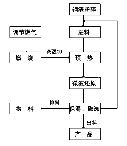
[0037] Embodiment two: see Figure 4 , using the magnetic separation device of Example 1 to magnetically separate hematite (Fe 2 o 3 ) method for materials, including the following steps:

[0038] Crush the hematite-containing material to 80-100 mesh powder, add it to the silo 1, the powder enters the preheating reaction furnace 5 through the screw feeder 2 and the star feeder 3 for preheating, and the preheated powder Enter the microwave magnetic separator 6 through the air inlet pipe 6-4 for microwave heat treatment and magnetic separation; the products after magnetic separation are discharged from the discharge port 12 through the ore discharge pipe 6-6, and other materials are discharged from the discharge port 12 through the air outlet pipe 6-5. Discharge from the material port 13; or first go through dust removal and then discharge from the discharge port.

[0039] The materials containing hematite can be steel slag, low-grade limonite, iron ore and other ores.

[00...

Embodiment 3

[0042] Embodiment three: see Figure 4 , utilize the method for magnetically separating steel slag of magnetic separation device, the magnetic separation device that adopts is as described in example one, and this method comprises the following steps:

[0043] Crush steel slag into 80-100 mesh powder, measure 100kg of powder and add it to silo 1, the powder in silo 1 goes through screw feeder 2 and star feeder 3, and enters preheating reaction furnace 5 for preheating ;

[0044] Adjust the gas in the gas storage tank 9 and the air blown in by the blower 10, and burn in the combustion chamber 4 after being mixed by the burner 11, and the CO high-temperature gas produced after combustion enters from the bottom of the preheating reaction furnace 5 to preheat the material;

[0045] After the preheated material reaches 300°C, it enters the microwave magnetic separator 6 through the air inlet pipe 6-4 for microwave heat treatment. The microwave power is 15KW. Adjust the microwave o...


PUM


Abstract

The invention relates to a device and a method for reducing hematite-containing materials by utilizing microwave heat treatment and carrying out magnetic separation. The device comprises a material bin, a screw feeder, a star type feeding machine, a preheating reacting furnace and a microwave magnetic separator. When the magnetic separation is carried out, the materials are crushed and then added to the material bin, powdery materials enter the preheating reacting furnace through the screw feeder and the star type feeding machine for preheating, and the preheated powdery materials enter the microwave magnetic separator through an air inlet pipe for the microwave heat treatment and the magnetic separation; products subjected to the magnetic separation are discharged through an ore discharge pipe from a discharge port, and other materials are discharged through an outlet pipe from the discharge port. The device disclosed by the invention can be used for reducing the weak magnetic Fe2O3 contained in the materials into strong magnetic Fe3O4 through the microwave heating and separating the iron ore concentrates through the magnetic separation, integrally and simultaneously carries out the reduction and the magnetic separation, has the advantages of small investment, low energy consumption, large treatment quantity, water saving, no air pollution, wide application range and relatively popularization prospect, is simple in equipment, and can be used for treating multiple hematite-containing materials which include ores, such as steel slag, low-grade limonite and iron ores.

Description

technical field [0001] The invention relates to a magnetic separation device and a magnetic separation method for separating hematite-containing materials, in particular to a device and a magnetic separation method for reducing hematite-containing materials by microwave heat treatment and performing magnetic separation. Background technique [0002] Steel slag is the waste slag produced in the steelmaking process, and the amount is about 15-20% of the steel output. In recent years, with the rapid development of my country's iron and steel industry, the discharge of steel slag has also increased. A large amount of steel slag needs a large area of ​​land to be piled up every year, which brings serious pollution to soil, water body, atmosphere, etc., and even poses a threat to people's health. However, in fact, the useful components in the steel slag account for the vast majority, as long as the harmful components in the steel slag are removed, it can be comprehensively utiliz...

Claims


Application Information

Patent Timeline
Patent Type & Authority Applications(China)
IPC IPC(8): B03C1/00B03C1/015C22B1/00
Inventor 张雪峰李保卫贾晓林王建英李超罗家骏
Owner INNER MONGOLIA UNIV OF SCI & TECH
Learn More