Eureka AIR delivers breakthrough ideas for toughest innovation challenges, trusted by R&D personnel around the world.

Liquid phase impinging stream reactor with controllable acidity

A technology of impinging flow reaction and reaction device, which is applied in the direction of chemical/physical/physical chemical fixed reactors, etc., can solve problems such as unfavorable unloading and cleaning, vibration of propeller and motor shaft, and unsuitability for long-term operation, etc., to achieve Ensure continuous and stable operation, large circulation volume and simple structure

Active Publication Date: 2013-07-17
TSINGHUA UNIV
View PDF4 Cites 18 Cited by
  • Summary
  • Abstract
  • Description
  • Claims
  • Application Information

AI Technical Summary

Problems solved by technology

Thirdly, the motor shaft driving the propeller is a cantilever structure. If the shaft is long or the speed is fast, it will easily cause vibration of the propeller and the motor shaft, and the deformation of the shaft will cause the motor to not work, which is not suitable for long-term operation.
In addition, there is a vortex flow in the fluid in the guide tube, and a vortex is generated in the flow, resulting in a large amount of energy loss
Finally, the bottom of the container is designed horizontally. For systems with solid particles or crystallization, it is not conducive to unloading and cleaning the container after the reaction.

Method used


Image

  • Liquid phase impinging stream reactor with controllable acidity
  • Liquid phase impinging stream reactor with controllable acidity
  • Liquid phase impinging stream reactor with controllable acidity

Examples


Embodiment 1

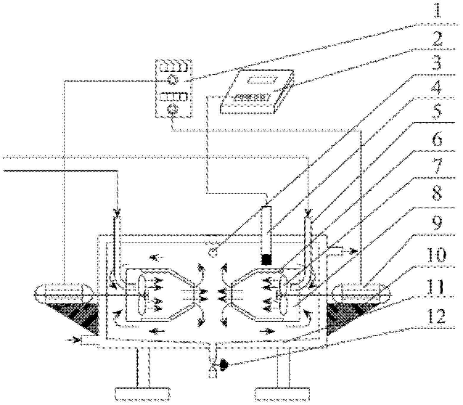
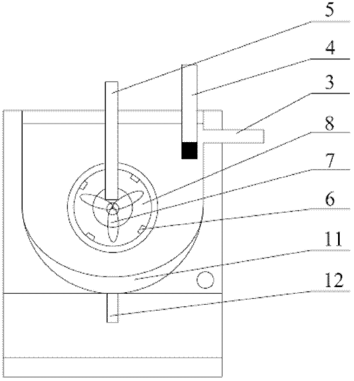
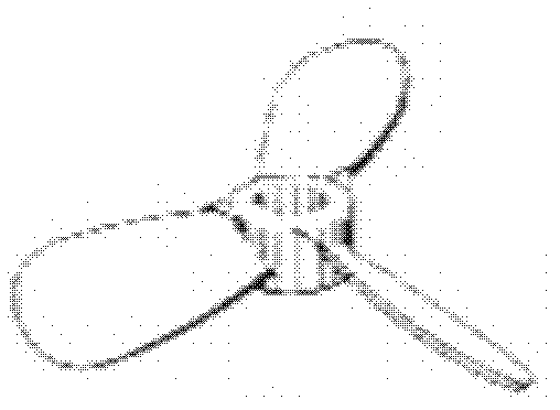
[0029] An acidity controllable liquid phase impinging stream reaction device. The reactor of this device is a horizontal structure, including a reactor shell 11, which is a jacket type, which is convenient for heating or cooling. Two coaxial variable-diameter diversion cylinders 8 are installed symmetrically in the middle of the left and right sides of the reactor shell 11. The diversion cylinders 8 are variable-diameter, and the diameter of the outlet end of the diversion cylinder 8 is 3 / 4 of the diameter of the inlet end. , There is enough space between the inlet of the deflector 8 and the inner wall of the reaction shell 11 to be used as a material circulation flow channel. At the feed end of the deflector 8 are installed a push-type three-blade agitator 7 and two agitators 7 respectively. Coaxial symmetry, used to accelerate the fluid. An elbow feeding tube 5 is provided at the entrance of the deflector 8 and the raw materials are input through the elbow feeding tube 5, whi...

Embodiment 2

[0032] The reaction device is the same as in Example 1.

[0033] Fill the reactor with deionized water, turn on the heat carrier circulation switch, conduct a constant temperature water bath through the jacket of the reactor shell and set the temperature to 60°C, turn on the speed controller 1 so that the motor 9 drives the stirrer 7 and adjust the speed to 2000r·min -1 After the temperature of the working fluid in the reactor reaches 60℃, use a metering pump to reduce the mixed solution of ferric nitrate and phosphoric acid to 0.1L·min -1 The flow rate is fed into the reactor through a feeding pipe with a side elbow, and the concentration of ferric nitrate and phosphoric acid in the mixed solution are both 0.1mol·L -1 , And at the same time input 0.2mol·L through another elbow feeding tube -1 The pH value of the reaction system is controlled by the aqueous ammonia solution to 2.3. After the process is stabilized, the products at 3 outlets of the reactor are collected, and the sphe...

Embodiment 3

[0035] The reaction device is the same as in Example 1. Fill the reactor with deionized water, turn on the heat carrier circulation switch, conduct a constant temperature water bath through the jacket of the reactor shell and set the temperature to 50°C, turn on the speed controller 1 to make the motor 9 drive the agitator 7 and adjust the speed to 2900r·min -1 , After the temperature of the working fluid in the reactor reaches 50℃, use a metering pump to reduce the concentration to 0.1mol·L -1 The mixed solution of ferrous nitrate and phosphoric acid in 0.1L·min -1 The flow rate is fed into the reactor through one side elbow feeding tube, and at the same time, 4mol·L is input through the other elbow feeding tube -1 The pH value of the reaction system is controlled by the aqueous ammonia solution at 4.5. After the process is stabilized, the product at the outlet of the reactor is collected, and the spherical nano-scale iron phosphate is obtained after post-processing procedures s...


PUM


Abstract

The invention discloses a liquid phase impinging stream reactor with controllable acidity, belonging to the field of chemical reaction technical equipment. In the reactor, 1-6 pairs of draft tubes with changeable diameters are horizontally arranged coaxially and oppositely; raw materials are introduced by feeding tubes with curved nozzles; fluid is accelerated by push-type three-blade stirrers at the entrance of the draft tubes; the rotation speed of the push-type three-blade stirrers is controlled by a controller; rotational flow is inhibited by deflection baffles; the inner diameters of the draft tubes become smaller gradually; cross-section area of a flow channel is decreased; flow speed is increased; the flow speed at the exits of the draft tubes is the maximum; two fluids impinge face to face at a high speed in the container and mixed efficiently and rapidly; the fluids flow to the entrance of the draft tubes from central impinging areas through the outer sides of the draft tubes, thus realizing circulation; motors are fixed and anti-vibrated by triangle support plates, the acidity of a reaction system is on-site monitored by a pH meter probe and displayed in real time by a pH meter display; constant acidity of the reaction system is realized by adjusting liquid inlet flow quantity; and materials in the contained are discharged from a material-discharging port after the reaction is finished. The liquid phase impinging stream reactor can be heated or cooled, and can be operated continuously, intermittently or semi-continuously.

Description

Technical field [0001] The invention belongs to the field of chemical reaction technology and equipment, and relates to an acidity controllable liquid phase impinging stream reaction device. Background technique [0002] The process of preparing ultra-fine powder by liquid phase reaction is often involved in engineering fields such as chemical engineering, materials and pharmacy. The problem of rapid and uniform mixing of materials in the reaction device is the bottleneck of the quality of the prepared products in this process, which directly affects the particle size and size distribution of the product particles . [0003] The traditional device widely used in the liquid phase reaction process in the industry is the tank-type stirred tank reactor. This type of reactor is often in a vessel whose height is slightly larger than the diameter. The stirring blade drives the fluid to rotate, so that the flow groups are generated. Mixing occurs due to relative movement. Because the rel...

Claims


Application Information

Patent Timeline
Patent Type & Authority Applications(China)
IPC IPC(8): B01J19/18
Inventor 蒲薇华肖杨武玉玲邓长生
Owner TSINGHUA UNIV
Why Eureka
Eureka Blog
Learn More