Power supply system and power supply unit thereof

An electric energy supply system and electric energy supply technology, applied in the manufacture of electrical components, non-aqueous electrolyte batteries, and electrolyte batteries, etc., can solve problems such as poor yield and reliability of welding projects, reduced efficiency of battery cells, and difficult contact conditions. To achieve the effect of simplifying the assembly and manufacturing engineering, reducing the manufacturing process, and reducing the number of interfaces

Active Publication Date: 2013-07-03
PROLOGIUM TECH +1
View PDF3 Cites 2 Cited by
  • Summary
  • Abstract
  • Description
  • Claims
  • Application Information

AI Technical Summary

Problems solved by technology

[0004] However, because whether the contact interface between the isolation layer 11 and the first active material layer 12 and the second active material layer 13 has a good contact has a very direct and serious impact on the electrical properties and safety performance of the overall battery system, so The management of the interface can be said to be a key factor affecting the stability and safety of the battery system; as shown in Figure 1, the existing lithium battery includes a first collector layer 14, a first active material layer 12, a first active material layer 12 and the isolation layer 11, the isolation layer 11 and the second active material layer 13, and the second active material layer 13 and the second collector layer 15 four interfaces, therefore, in the existing lithium battery technology in order to maintain these interfaces Whether it is a battery core with a stacked structure or a wound structure, the flexibility of the overall structure after the battery is assembled is quite low, or even impossible to bend. The reason is to avoid bending The stress of the above-mentioned interface is destroyed, so as to maintain the electrical performance of the lithium battery system and ensure its safety in use
[0005] Furthermore, the negative electrode material will heat up and expand / shrink during the charging / discharging process. Once expanded, it will inevitably generate additional compressive stress to the structure on both sides. From this structure, it is assumed that the second active material layer 13 is the negative electrode material. The second active material layer 13 is sandwiched between the isolation layer 11 and the second collector layer 15, so it is limited by the isolation layer 11 and the second collector layer 15, so that the compressive stress cannot be released. It is more difficult to maintain the contact state between the interfaces after repeated expansion and contraction
In addition, the general conductive handle is made of aluminum metal. The aluminum electric handle needs to be ultrasonically welded with the nickel sheet before the positive electrode conductive handle can be tin-welded (because aluminum cannot be soldered directly), and the conductive handle needs to be extended outward. For the packaging material, its thickness is about 100~150um, and the total thickness of the upper and lower colloids of the packaging material is about 60~120um. The water vapor in the environment diffuses and pollutes the interior) and the effect of liquid resistance (the internal electrolyte overflows and corrodes the external circuit) is seriously reduced
[0006] For battery cells with a stacked or wound structure, please refer to Figure 2. In the figure, the stacked structure is used as an example for illustration. Because a single battery cell has four interfaces, the number of interfaces is reduced by the addition of mutual stacking. It increases cumulatively in multiples; coupled with the problem of thermal expansion / contraction of the negative electrode material as mentioned above, once one of the interfaces is not in good contact, it may affect the reliability of the overall battery system
And the existence of the interface will also affect the flow and permeability of the electrolyte. The more interfaces, the more difficult it is for the filled electrolyte to penetrate the entire battery system evenly. Either it takes more time to penetrate, or it is difficult to penetrate evenly, resulting in partial battery cell efficiency. reduce
[0007] On the other hand, as shown in Figure 2, when the battery system is formed by stacking, it is equivalent to the need for parallel connection of multiple batteries inside, and the inner tabs of each battery 1 must be welded to each other first, and then connected to the single conductive handle of the two poles. Welding, so once the number of tabs increases, the yield and reliability of the overall welding project will also deteriorate

Method used


Image

  • Power supply system and power supply unit thereof
  • Power supply system and power supply unit thereof
  • Power supply system and power supply unit thereof

Examples


Embodiment Construction

[0059] In order to further explain the technical solution of the present invention, the present invention will be described in detail below through specific examples.

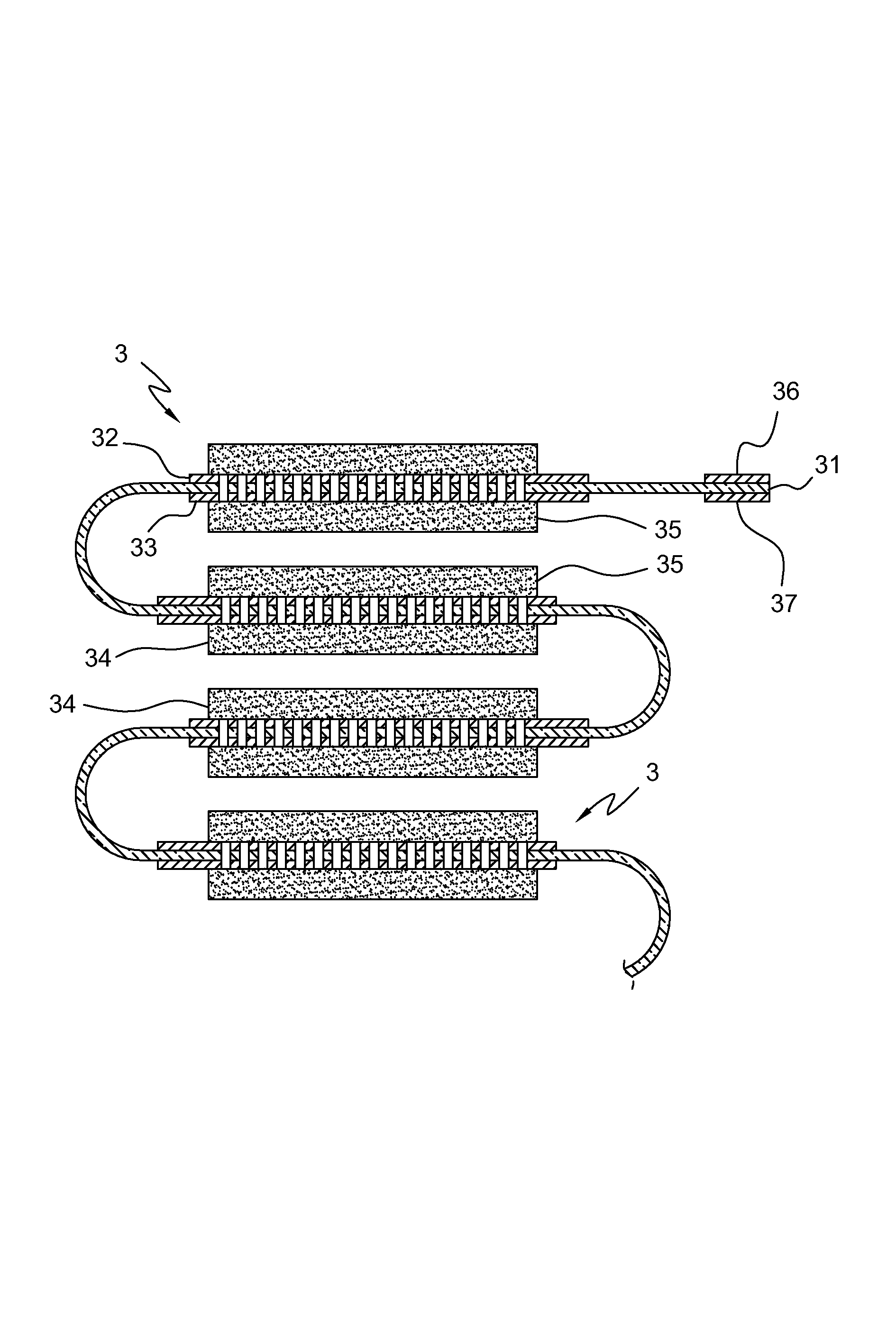
[0060] Please refer to FIG. 2 , which is a schematic cross-sectional view of a power supply unit according to a preferred embodiment of the present invention. The power supply unit 3 includes a substrate 31, a first collector layer 32, a second collector layer 33, a first active material layer 34, and a second active material layer 35, wherein the substrate 31 includes an isolated conduction region 311 and a phase The adjacent external line connection area 312 has a plurality of micro-holes 313 on the isolation conduction area 311, and the first collector layer 32 is located on one side of the substrate 31, and has a plurality of micro-holes 313 corresponding to the isolation conduction area 311. The micro-holes 321 ; the second collector layer 33 is located on the other side of the substrate 31 and has a plura...


PUM


Abstract

The present invention discloses a power supply system and power supply units thereof. The power supply system is formed by mutual winding / stacking of a plurality of power supply units. Each power supply unit includes a substrate, two power collection layers, and two active material layers, wherein the substrate is provided with a plurality of micro holes, the power collection layers and the active material layers are stacked and covered on both sides of the substrate in order, therefore direct conduction of ions is achieved by micro holes in the substrate, and the generated power is directly transmitted outward by the power collection layers. A power supply mode of a novel form is used for reducing the impedance value of a power supply system. Because the power collection layers are located at two sides of the substrate, a coating process is only needed to complete the arrangement of the power collection layers and the isolation layers, and the production process of the power collection layer and the isolation layers are greatly simplified.

Description

technical field [0001] The invention relates to an electric energy supply system and an electric energy supply unit applied to power supply of various electronic devices. Background technique [0002] As 3C products such as electronics, information and communication are all developing towards wireless and portable, various high-performance components used in various products are moving towards the goal of lightness, thinness, shortness and smallness. In recent years, flexible The technological development of electronic products has gradually been paid attention to. Therefore, the demand for power supply systems with small size, light weight and high energy density is quite urgent. However, in order to prolong the battery life and increase the energy density of the battery, the primary battery system that could not be reused in the past can no longer meet the needs of today's electronic products, and most of the battery systems currently used in electronic products are rechar...

Claims


Application Information

Patent Timeline
IPC IPC(8): H01M10/04H01M10/058H01M2/14
CPCY02E60/10Y02P70/50
Inventor 杨思枬
Owner PROLOGIUM TECH
Why Eureka
Try Eureka