NdFeB (neodymium iron boron) magnetic material with ultrafine powder and preparation method thereof
A magnetic material and ultrafine powder technology, which is applied in the direction of magnetic materials, magnetic objects, and inorganic materials, can solve the problems of ultrafine powder storage, danger and difficulty in use, low residual magnetization, and easy oxidation and combustion. Achieve the effects of improving comprehensive economic benefits, inhibiting grain growth, and protecting the environment
- Summary
- Abstract
- Description
- Claims
- Application Information
AI Technical Summary
Problems solved by technology
Method used
Image
Examples
Embodiment 1
[0028] Configure conventional alloys, the mass percentage composition of raw materials is: Pr-Nd-Dy: 25.5%, La-Ce: 5%, B: 1.0%, Fe: 67.5%, Al: 0.8%, Cu: 0.2%, using SC- Preparation of conventional alloy coarse particle powder by HD process: at 3.0×10 -1 Melted into thin slices with a thickness of 0.25-0.35mm under Pa vacuum, the thin slices absorb hydrogen at room temperature for 3.0 hours in the reaction kettle of the hydrogen crushing furnace, and then heat to 600°C for 6.0 hours to dehydrogenate to prepare a particle size of 60-80 mesh. Coarse powder for use;
[0029] The ultra-fine powder produced by the jet mill is uniformly mixed in the mixer for 1-3 hours.
[0030] The above-mentioned alloy coarse particle powder is ground by a QLM-400 jet mill under a working pressure of 0.7MPa to a fine powder with an average particle size of 3.0-3.5μm; %) ratio, add 15-20% of the above-mentioned superfine powder to the conventional alloy powder, and mix evenly in the mixer for 2 ho...
Embodiment 2
[0036] The difference from Example 1 is that the addition ratio of superfine powder is 10%, and other process routes are the same as in Example 1, and the test data are shown in Table 1.
[0037] The topography diagram relevant to this embodiment is similar to that of Embodiment 1, omitted.
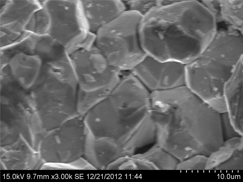
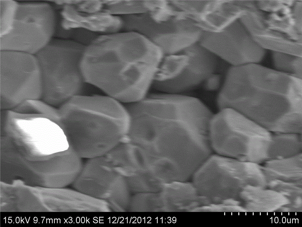
[0038] as the picture shows, Figure 1-3 The microscope (SEM) topography in the figure is the scanning electron microscope (SEM) topography of the magnet after adding 10% (wt%) ultrafine powder and sintering; Figure 2-3The curve in is the magnetization characteristic curve of 10% (wt%) superfine powder addition, which is shown by No. 3 in the test data in Table 1. Compared with the curve without superfine powder: the coercive force of the finished product is increased by 32.6 %, the squareness increased by 9.1%, and the residual magnetism decreased by 4.5%.
Embodiment 3
[0040] The difference from Example 1 is that the addition ratio of superfine powder is 15%, and other process routes are the same as in Example 1, and the test data are shown in Table 1.
[0041] The topography diagram relevant to this embodiment is similar to that of Embodiment 1, omitted.
[0042] as the picture shows, Figure 1-4 The microscope (SEM) topography in the figure is the scanning electron microscope (SEM) topography of the magnet after adding 15% (wt%) ultrafine powder and sintering; Figure 2-4 The curve in is the magnetization characteristic curve of 15% (wt%) superfine powder addition, which is shown in No. 4 of the test data in Table 1. Compared with the curve without superfine powder: the coercive force of the finished product is improved 38.3%, the squareness increased by 10.6%, and the residual magnetism decreased by 7.3%.
PUM
| Property | Measurement | Unit |
|---|---|---|
| particle size | aaaaa | aaaaa |
| particle size | aaaaa | aaaaa |
Abstract
Description
Claims
Application Information
 - R&D
- Intellectual Property
- Life Sciences
- Materials
- Tech Scout
- Unparalleled Data Quality
- Higher Quality Content
- 60% Fewer Hallucinations
Browse by: Latest US Patents, China's latest patents, Technical Efficacy Thesaurus, Application Domain, Technology Topic, Popular Technical Reports.
© 2025 PatSnap. All rights reserved.Legal|Privacy policy|Modern Slavery Act Transparency Statement|Sitemap|About US| Contact US: help@patsnap.com


