Magneto-rheological effect viscoelastic clamping electroceramic substrate flexible grinding and polishing device and method
A magneto-rheological effect and viscoelasticity technology, applied in the field of flexible lapping and polishing devices for electric ceramic substrates, can solve problems such as difficult clamping, high substrate breakage rate, and easy breakage, etc., to achieve zero clamping breakage rate, loading The clip is safe and reliable, and the effect of improving the grinding effect
- Summary
- Abstract
- Description
- Claims
- Application Information
AI Technical Summary
Problems solved by technology
Method used
Image
Examples
Embodiment
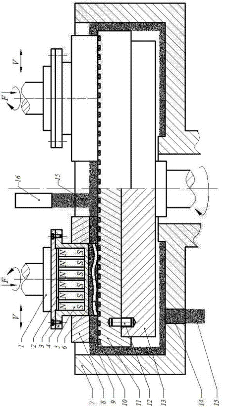
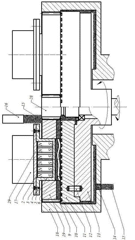
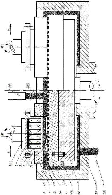
[0038] The structure diagram of the present invention is as figure 1 , 2 , 3, and 4, the magneto-rheological effect viscoelastically clamped flexible polishing device for electroceramic substrates of the present invention includes a grinding head spindle 1, a substrate 2, a fixing screw 3, and has a substrate with an ultra-thin hard and brittle material. 6 magnetic sleeves 4 with the same shape and size, high magnetic induction magnetic body 5, grinding disc trimming set 8, grinding disc 11, grinding disc main shaft 13, wherein the fixing screw 3 is inlaid with the substrate 2 arranged with the high magnetic induction intensity magnetic body 5 Fixed on the magnetic sleeve 4 to form a flexible grinding and polishing head, the grinding disc 11 is fixed on the grinding disc spindle 13, the grinding disc dressing set 8 is placed on the grinding disc 11, and the magnetorheological working fluid 15 is added to the grinding disc 11 through the circulation pipe 16 of the upper surfa...
Embodiment 1
[0059] Step 1: If figure 1 As shown, by the aluminum material grinding head main shaft 1, the aluminum material magnetic cover 4 and the fixing screw 3 that have the same shape and size as the ultra-thin hard and brittle material substrate 6 will press Figure 7 or Figure 8 The iron plate substrate 2 with the high magnetic induction intensity magnetic body 5 of 3000GS arranged according to the pattern shown is inlaid and fixed on the magnetic sleeve 4 to form a flexible grinding and polishing head;
[0060] Step 2: adding 20% by weight of carbonyl iron powder with an average particle diameter of 5 microns in deionized water, and 8% by weight of SiO with an average particle diameter of 5 microns 2 Abrasives, 5% by weight glycerin, 5% by weight antirust agent, fully stirred to form magnetorheological fluid 15;
[0061] Step 3: Fix the grinding disc 11 on the grinding disc main shaft 13 through the pin 12, and then place the Figure 9 or Figure 10 The shown trimming surf...
Embodiment 2
[0069] Step 1: If figure 2 As shown, by having the aluminum material magnetic sleeve 4 that is consistent with the shape and size of the ultra-thin hard and brittle material substrate 6, the fixing screw 3 and the aluminum material end cap 29 press Figure 7 or Figure 8 The iron plate substrate 2 with the high magnetic induction intensity magnetic body 5 of 4000GS is arranged regularly and fixed on the magnetic sleeve 4 to form a flexible grinding and polishing head;
[0070] Step 2: adding 20% by weight of carbonyl iron powder with an average particle diameter of 3 microns in deionized water, and 8% by weight of SiO with an average particle diameter of 3 microns 2 Abrasives, 5% by weight glycerin, 5% by weight antirust agent, fully stirred to form magnetorheological fluid 15;
[0071] Step 3: Fix the grinding disc 11 on the grinding disc main shaft 13 through the pin 12, and then place the Figure 11 or Figure 12 The shown trimming surface 6 has a rectangular groove ...
PUM
 Abstract
Description
Claims
Application Information
 - R&D
- Intellectual Property
- Life Sciences
- Materials
- Tech Scout
- Unparalleled Data Quality
- Higher Quality Content
- 60% Fewer Hallucinations
Browse by: Latest US Patents, China's latest patents, Technical Efficacy Thesaurus, Application Domain, Technology Topic, Popular Technical Reports.
© 2025 PatSnap. All rights reserved.Legal|Privacy policy|Modern Slavery Act Transparency Statement|Sitemap|About US| Contact US: help@patsnap.com


