
Ladle working liner and preparation method thereof

A technology of working lining and ladle, applied in metal processing equipment, manufacturing tools, casting equipment, etc., can solve the problems of iron infiltration in brick joints, easily damaged working lining bricks, and asynchronous working lining life.

Inactive Publication Date: 2014-01-15
LAIWU IRON & STEEL GRP
View PDF5 Cites 0 Cited by
  • Summary
  • Abstract
  • Description
  • Claims
  • Application Information

AI Technical Summary

Problems solved by technology

However, there are new common technical problems in the practical application of aluminum carbide silicon unburned bricks: (1) The oxidation resistance of aluminum carbide silicon unburned bricks is poor, especially during the baking process, the surface of aluminum carbide silicon unburned bricks Heavy oxidation; (2) The problem of iron seepage in the joints of aluminum carbide silicon unburned bricks; (3) The bottom of the molten iron ladle and the working lining at the lower part of the ladle wall scoured by the molten iron injection flow, the damage rate is high, and the local erosion and erosion are heavy. It is not synchronized with the life of the working lining of other parts; (4) It is difficult to deal with the sticky slag along the molten iron ladle, and it is easy to damage the working lining bricks along the ladle, and it is forced to go offline for repairs, which affects the service life and turnover of the working lining of the molten iron ladle Use, and increase the cost of ladle refractories
However, it does not involve the comprehensive masonry process of the ladle

Method used


Image

  • Ladle working liner and preparation method thereof

Examples


Embodiment 1

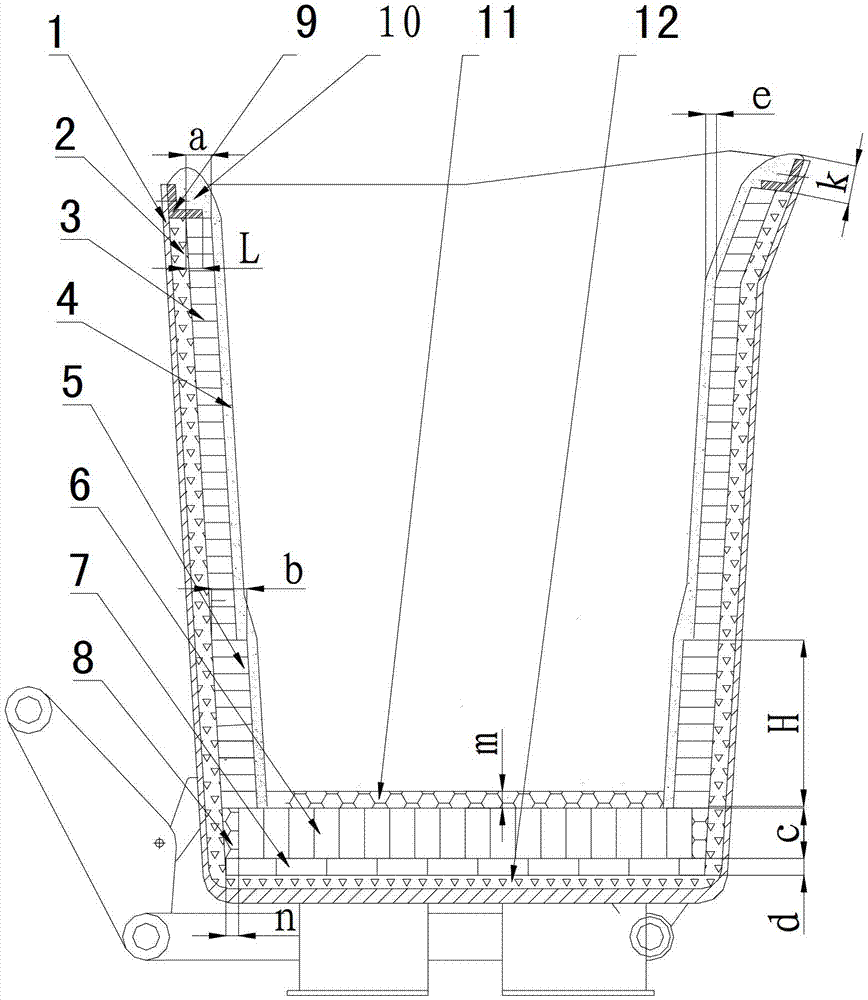
[0052] Such as figure 1As shown, a ladle working lining, the ladle working lining is installed in the ladle shell 1, the ladle wall permanent lining 2 and the ladle bottom permanent lining 12, the ladle working lining is laid on the inner wall of the ladle shell 1 and the cladding wall is permanently Lining 2, ladle bottom permanent lining 12 is laid on the bottom of ladle shell 1. Including flat-laying refractory bricks for the bottom-covering working lining 7, vertical-laying refractory bricks for the bottom-covering working lining 6, castables for the bottom-covering working lining 11, working lining refractory bricks for the iron flow impact area of ​​the lower part of the wrapping wall, and 5 working lining refractory bricks for the upper part of the wrapping wall and wall covering smear 4; it is characterized in that, on the bottom of the permanent lining 12, from bottom to top, it is the bottom working lining flat laying refractory brick 7, the bottom working lining ver...

Embodiment 2

[0083] Others are the same as embodiment 1, the difference is:

[0084] The ladle working lining also includes a ladle edge pressing plate 9 located on the upper part of the ladle shell 1; a ladle edge smear layer 10 is applied on the upper part of the ladle edge pressing plate (9).

[0085] The working lining of the molten iron ladle is 30mm thicker than the working lining refractory brick 3 of the upper part of the ladle wall in the iron flow impact zone of the lower part of the ladle wall.

[0086] The thickness d of the flat-laying refractory brick 7 for the bottom-covering working lining is 120 mm, the thickness c of the vertical-laying refractory brick 6 for the bottom-covering working lining is 300 mm, and the thickness m of the bottom-covering working lining castable 11 is 60 mm.

[0087] The thickness a of the working lining refractory brick 3 on the upper part of the cladding wall is 140 mm, and the thickness b of the working lining refractory brick 5 in the impact are...

Embodiment 3

[0107] Others are the same as embodiment 1, the difference is:

[0108] The working lining of the molten iron ladle is 25mm thicker than the working lining refractory brick 3 of the upper part of the ladle wall in the iron flow impact area of ​​the lower part of the ladle wall.

[0109] The thickness d of the flat-laying refractory brick 7 for the bottom-covering working lining is 100mm, the thickness c of the vertical-laying refractory brick 6 for the bottom-covering working lining is 280mm, and the thickness m of the bottom-covering working lining castable 11 is 90mm.

[0110] The thickness a of the working lining refractory brick 3 on the upper part of the cladding wall is 130 mm, and the thickness b of the working lining refractory brick 5 in the iron flow impact area on the lower part of the cladding wall is 155 mm.

[0111] The coating material layer 4 thickness e of the cladding wall is 20mm

[0112] The thickness k of the coating material layer 10 along the package is...


PUM

PropertyMeasurementUnit
densityaaaaaaaaaa
compressive strengthaaaaaaaaaa
softening pointaaaaaaaaaa

Abstract

The invention relates to a ladle working liner and a preparation method thereof, and belongs to the technical field of a ferrous metallurgy ladle process. The ladle working liner is characterized in that a ladle bottom working liner consists of three layers of structures which are ladle bottom working liner flat laid refractory bricks (7), ladle bottom working liner vertical laid refractory bricks (6) and ladle bottom working liner castable (11) from bottom to top in sequence, wherein the iron flow impact region working liner refractory bricks (5) on the lower part of a ladle wall is 20-30 mm thicker than the working liner refractory bricks (3) on the upper part of the ladle wall; a ladle wall coating layer (4) is coated on the outer surfaces of the working liner refractory bricks (3) on the upper part of the ladle wall and the iron flow impact region working liner refractory bricks (5) on the lower part of the ladle wall; and a ladle edge coating layer (10) is coated on the upper part of a ladle edge pressing plate (9). By using the ladle working liner, the service life of the ladle working liner is prolonged by 300-400 heats and the ladle refractory material cost is reduced by over 30 percent on year-on-year basis.

Description

technical field [0001] The invention relates to a ladle working lining and a preparation method thereof, belonging to the technical field of iron and steel metallurgy ladle technology. Background technique [0002] The molten iron ladle is a container for shipping molten iron for steelmaking, and its inner lining generally includes a permanent lining and a working lining. At present, there are mainly two types of working linings for ladles: one is castable as a whole, and the other is built with high-alumina bricks or clay bricks. In recent years, aluminum carbide silicon unburned bricks have been gradually popularized and applied in domestic large and medium-sized ladle working linings due to their corrosion resistance, no slag hanging, good thermal stability and high cost performance. However, there are new common technical problems in the practical application of aluminum carbide silicon unburned bricks: (1) The oxidation resistance of aluminum carbide silicon unburned b...

Claims


Application Information

Patent Timeline
Patent Type & Authority Patents(China)
IPC IPC(8): B22D41/02C04B35/66
Inventor 武光君张其龙王金洪李运生朱秋菊
Owner LAIWU IRON & STEEL GRP
Learn More