
Multi-wavelength light source-based Brillouin optical time domain reflectometer

A technology of optical time domain reflectometry and multi-wavelength light source, which is applied to instruments, scientific instruments, optical devices, etc., can solve the problems of increasing system signal processing time, reducing measurement dynamic range, restricting system dynamic range, etc., so as to shorten the measurement time. The effect of time, signal-to-noise ratio improvement, and dynamic range improvement

Inactive Publication Date: 2012-07-18
NANJING UNIVERSTIY SUZHOU HIGH TECH INST +1
View PDF8 Cites 29 Cited by
  • Summary
  • Abstract
  • Description
  • Claims
  • Application Information

AI Technical Summary

Problems solved by technology

However, due to the limitation of the nonlinear effect in the optical fiber, the probing optical power incident on the optical fiber under test should be lower than the stimulated Brillouin threshold, and increasing the number of measurements will increase the measurement time, so the improvement of the dynamic range of the system is restricted
The spatial resolution of the measurement is mainly limited by the pulse width of the probe light, shortening the pulse width of the probe light can improve the spatial resolution, but it will reduce the dynamic range of the measurement
By means of pulse encoding, the measurement can have a large dynamic range and high spatial resolution at the same time, but this will greatly increase the signal processing time of the system

Method used


Image

  • Multi-wavelength light source-based Brillouin optical time domain reflectometer
  • Multi-wavelength light source-based Brillouin optical time domain reflectometer
  • Multi-wavelength light source-based Brillouin optical time domain reflectometer

Examples


Embodiment Construction

[0021] The measuring method of the present invention will be described below in conjunction with specific measuring methods and accompanying drawings. This embodiment uses three wavelengths, but the present invention is not limited to three wavelengths.

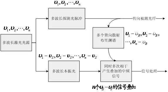
[0022] Such as image 3 As shown, the single-wavelength laser emits 1550nm single-wavelength laser light, which is modulated by the first electro-optic modulator (electro-optic modulator 1) and the first microwave source (microwave source 1) to generate laser light sources with three wavelengths, and the frequency interval Δv is 2GHz . After that, it is divided into two paths by the coupler, and one path is modulated into a 100ns optical pulse by the second electro-optic modulator (electro-optic modulator 2) and a pulse generator, and then amplified by an erbium-doped fiber amplifier, and enters the circulator 1 as a detection pulse light port, from the circulator 2 port to inject a 24km long optical fiber under test, about...


PUM


Abstract

The invention discloses a multi-wavelength light source-based Brillouin optical time domain reflectometer which comprises a multi-wavelength laser, a coupler, an electrooptical modulator, an erbium-doped optical fiber amplifier, an optical filter, a circulator, a double-balanced detector and a signal acquiring and processing system, wherein continuous light of the multi-wavelength laser is divided into two paths, wherein one path is modulated into pulse light through the electrooptical modulator and the other path is modulated to obtain continuous light of a local oscillator through an electrooptical modulator sideband. Multi-wavelength detection pulse light is amplified by the erbium-doped optical fiber amplifier, subjected to spontaneous emission noise filtration by the optical filter and is injected into a sensing optical fiber by the circulator. Stokes Brillouin back scattering light in the sensing optical fiber is coherent with local oscillator light through the circulator, is subjected to photovoltaic conversion through the double-balanced detector and then is fed into the signal acquiring and processing system to obtain a Brillouin scattering spectrum on the whole optical fiber and further obtain the temperature and strain distribution on the optical fiber.

Description

Technical field: [0001] The invention relates to a Brillouin optical time domain reflectometer used in the fields of optical fiber sensing and optical cable health monitoring. Background technique: [0002] At present, the Brillouin Optical Time Domain Reflectometer (BOTDR) based on coherent heterodyne detection uses a single-frequency narrow-linewidth light source. The probe light and local oscillator light are only single-frequency optical signals, and the obtained electrical signals are single-frequency detection. The scattering spectrum of the light and the coherent intermediate frequency broadband signal of the single-frequency local oscillator light, changing the center frequency of the local oscillator light, and collecting different frequency bands of the coherent intermediate frequency electrical signal spectrum each time, can obtain the Brillouin scattering spectrum of the optical fiber under test, through Lorentz fit to get the Brillouin frequency shift. By compa...

Claims


Application Information

Patent Timeline
Patent Type & Authority Applications(China)
IPC IPC(8): G01D5/36G01K11/32G01B11/16G01K11/322
Inventor 路元刚李存磊张旭苹
Owner NANJING UNIVERSTIY SUZHOU HIGH TECH INST
Learn More