Eureka AIR delivers breakthrough ideas for toughest innovation challenges, trusted by R&D personnel around the world.

Intelligent electric energy meter field test device and test method thereof

A smart energy meter and on-site detection technology, applied in the direction of measuring devices, measuring electrical variables, instruments, etc., can solve problems such as failure diagnosis of smart energy meters, economic losses of power supply companies and power users, etc., and improve utilization efficiency Effect

Inactive Publication Date: 2010-12-01
SHENYANG INST OF ENG
View PDF5 Cites 97 Cited by
  • Summary
  • Abstract
  • Description
  • Claims
  • Application Information

AI Technical Summary

Problems solved by technology

[0005] As a newly developed product, the smart energy meter has passed the test of the Electric Power Research Institute arranged by the State Grid, but it has not passed the test of on-site operation. The table brings a series of hidden dangers
Since the smart energy meter has multiple operating functions, and one or more of the functions fails, if the metering function is normal, the existing on-site detection devices, such as the electric energy meter field calibrator, etc., cannot perform other functions of the smart energy meter. Detection and Troubleshooting
Some smart electric energy meters run with diseases, and the electricity metering data is inaccurate, which brings unnecessary economic losses to both the power supply company and the power users.

Method used


Image

  • Intelligent electric energy meter field test device and test method thereof
  • Intelligent electric energy meter field test device and test method thereof

Examples


Embodiment Construction

[0020] The present invention will be further described below in conjunction with the drawings.

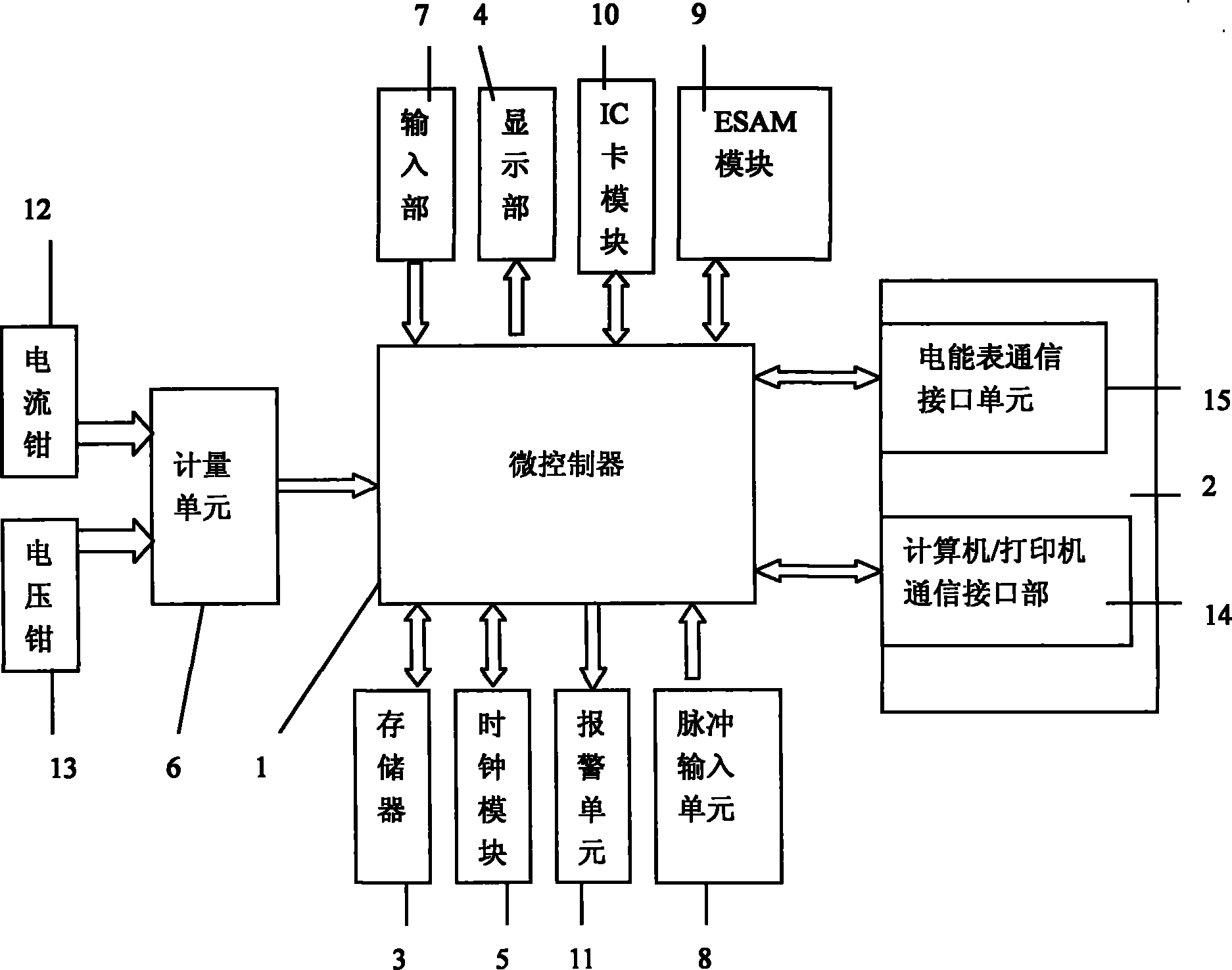
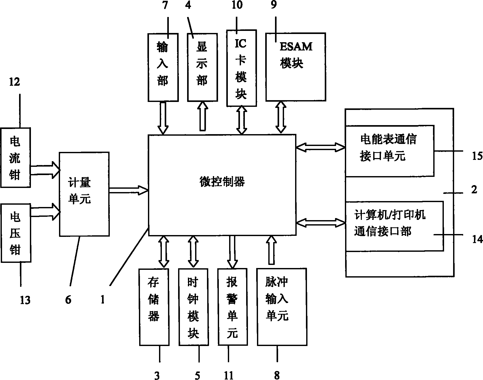
[0021] As shown in the figure, the intelligent electric energy meter field detection device of the present invention is composed of the following structure: a microcontroller 1, which receives control instructions from the input unit, and sends operation signals to the communication interface unit 2, the memory 3, the display unit 4 and the clock module 5. , And collect the original measurement data of the metering unit 6, compare the collected measurement data with the data received by the communication interface unit of the electric energy meter, determine whether the measured data of the electric energy meter is out of tolerance, and display the comparison result on the display unit 4; Unit 6, the analog signal transmitted from the current acquisition channel and the voltage acquisition channel, after filtering, amplifying, sampling and digital signal processing, is converted into d...


PUM


Abstract

The invention relates to an intelligent electric energy meter field test device and a test method thereof. The test device comprises a micro controller, a metering unit, a communication interface unit, a memorizer, an input part, a current acquisition channel and a voltage acquisition channel, a clock module and a pulse input unit; wherein the micro controller receives a control instruction of the input part and sends out an operation signal to the communication interface unit, the memorizer, a displaying part and the clock module; the metering unit carries out filtering, amplifying, sampling and digital signal processing on analogue signals transmitted by the current acquisition channel and the voltage acquisition channel, so as to convert the analogue signals into digital signals, and the digital signals are sent to the micro controller; the communication interface unit carries out data communication with an electric energy meter and downloads a user file from a server, and the user file is uploaded to the micro controller, and data of field test is uploaded and recorded into the server. The invention has the advantage that whether all the functions of intelligent electric energy meter are in normal operation or not can be determined by virtue of field test and diagnosis without interruption of power supply, modifying field primary and secondary loops or changing the state of the relay of the electric energy meter.

Description

Technical field [0001] The invention relates to a detection device, in particular to a field detection device and a detection method for an intelligent electric energy meter. Background technique [0002] In recent years, my country has attached great importance to the construction of smart grids. Premier Wen Jiabao emphasized in the 2010 government work report that it is necessary to "vigorously develop low-carbon technologies, promote high-efficiency energy-saving technologies, actively develop new and renewable energy sources, and strengthen the construction of smart grids." [0003] Smart grids will promote the realization of "interactive" power consumption-grid companies and users interact to regulate peak power consumption. This interactive way of power consumption requires the electric energy meter to have functions such as two-way metering, rate control, and communication. Therefore, smart electric energy meters have emerged. [0004] In October 2009, the State Grid Corpora...

Claims


Application Information

Patent Timeline
IPC IPC(8): G01R35/04
Inventor 田卫华王占元
Owner SHENYANG INST OF ENG
Why Eureka
Eureka Blog
Learn More