Solar battery and method of manufacturing the same
A technology for solar cells and manufacturing methods, applied to circuits, photovoltaic power generation, electrical components, etc., can solve the problems of reducing the effect of suppressing reflection, reducing the content of Pd on the surface side, increasing the resistivity value, etc., and achieving the reduction of the effect of suppressing reflection , The effect of photoelectric conversion efficiency improvement and output current increase
- Summary
- Abstract
- Description
- Claims
- Application Information
AI Technical Summary
Problems solved by technology
Method used
Image
Examples
Embodiment approach 1
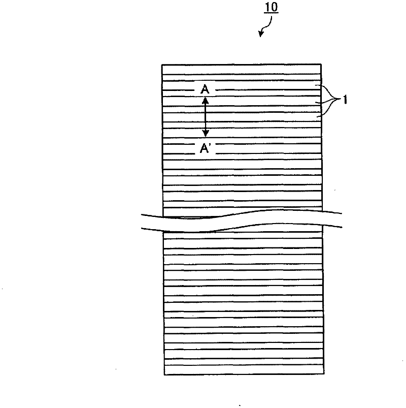
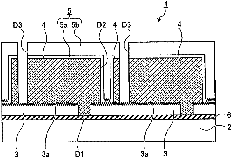
[0048] Picture 1-1 It is a plan view showing a schematic configuration of a thin-film solar cell module (hereinafter referred to as a module) 10 as a thin-film solar cell according to Embodiment 1 of the present invention. Figure 1-2 is a diagram for explaining the cross-sectional structure in the width direction of a thin-film solar battery cell (hereinafter, sometimes referred to as a cell) 1 constituting the module 10, and is Picture 1-1 Sectional view of the main part in the direction of the line segment A-A'.
[0049] Such as Picture 1-1 as well as Figure 1-2 As shown, the module 10 of Embodiment 1 has a structure including a plurality of rectangular (rectangular) cells 1 formed on a translucent insulating substrate 2 , and these cells 1 are electrically connected in series. Unit 1 has as Figure 1-2 As shown, the translucent insulating substrate 2, the transparent electrode layer 3 formed on the translucent insulating substrate 2 as the first electrode layer, the p...
manufacture example
[0066] Using an alloy target composed of Ag-1.5at%Mo, nitrogen (N 2) gas was sputtered in a plasma atmosphere of a mixed gas obtained by forming an Ag-Mo-N alloy film containing nitrogen with a film thickness of 200 nm. When the composition of the prepared sample was analyzed by inductively coupled plasma (Induced Coupled Plasma; abbreviation: ICP) emission analysis method and X-ray photoelectron spectroscopy (abbreviation: XPS) method, no matter which sample , the molybdenum composition ratio is 1.5at% Mo. The nitrogen composition ratio is the nitrogen (N 2 ) The gas partial pressure ratio changes between 1.3 at% and 5.5 at% correspondingly. In addition, nitrogen atoms exist in a substantially uniform concentration in the film.
[0067] From the above results, it can be seen that the Ag alloy film containing nitrogen in the range of 1.3 at % to 5.5 at % can be controlled by controlling the amount of N in the mixed gas when sputtering. 2 The partial pressure of the gas can...
Embodiment approach 2
[0161] In this embodiment, a case where the present invention is applied to a solar cell obtained by processing the surface of a single crystal silicon substrate or a polycrystalline silicon substrate (hereinafter referred to as a silicon substrate type solar cell) will be described. That is, an example will be described in which a photoelectric conversion layer made of a silicon substrate is provided and the technology of the present invention is applied to a reflective layer portion for rereflecting light passing through the photoelectric conversion layer to the photoelectric conversion layer.
[0162] Figure 9 It is a cross-sectional view for explaining the structure of the silicon substrate type solar cell 20 according to the second embodiment. The silicon substrate type solar cell 20 of the present embodiment includes: a semiconductor substrate 21 having a PN junction as a solar cell substrate having a photoelectric conversion function; The anti-reflection film 24 that ...
PUM
 Abstract
Description
Claims
Application Information
 - R&D
- Intellectual Property
- Life Sciences
- Materials
- Tech Scout
- Unparalleled Data Quality
- Higher Quality Content
- 60% Fewer Hallucinations
Browse by: Latest US Patents, China's latest patents, Technical Efficacy Thesaurus, Application Domain, Technology Topic, Popular Technical Reports.
© 2025 PatSnap. All rights reserved.Legal|Privacy policy|Modern Slavery Act Transparency Statement|Sitemap|About US| Contact US: help@patsnap.com


