Pultrusion method and equipment for thermoplastic composite material of continuous fiber
A technology of continuous fibers and composite materials, applied in the field of pultrusion molding methods and equipment for thermoplastic composite materials, which can solve problems such as harmful chemical solvents, rough surface of products, failure to achieve mechanical strength, etc., and achieve safe and reliable equipment and simple and easy methods The effect of row and continuous mass production
- Summary
- Abstract
- Description
- Claims
- Application Information
AI Technical Summary
Problems solved by technology
Method used
Image
Examples
Embodiment 1
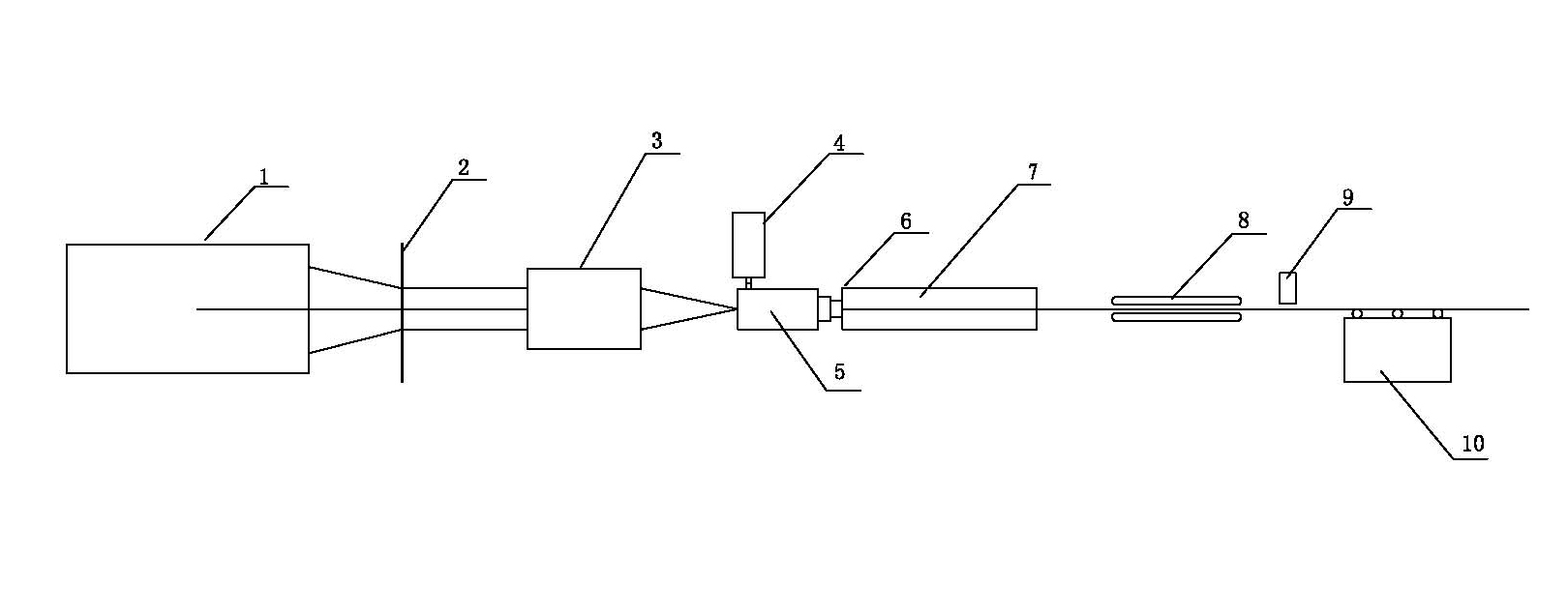
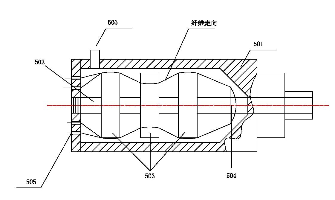
[0030] like figure 1 , 2 shown.
[0031] A kind of pultrusion molding method of the thermoplastic composite material of continuous fiber, it comprises the following steps:
[0032] Firstly, the continuous fiber of thermoplastic composite material is drawn from the constant tension creel 1 through the yarn collecting plate 2 and sent to the dehumidifier 3 for dehumidification, and the moisture content of the continuous fiber is controlled below 3%;
[0033] Secondly, the dehumidified continuous fiber is sent into the impregnator 5 for impregnation; the impregnator 5 is mainly composed of a housing 501, an adjustment shaft 502, a fiber spreader 503 and a resin content controller 504, and the housing 501 is close to the dehumidifier 3 One end of the housing 501 is provided with a fiber perforated plate 505 for the continuous fiber after dehumidification to penetrate, and the other end of the shell 501 is provided with a fiber outlet hole for the impregnated continuous fiber to ...
Embodiment 2
[0048] like figure 1 , 2 shown.
[0049] A pultrusion molding equipment for continuous fiber thermoplastic composite materials, which includes a constant force creel 1, a yarn collecting plate 2, a dehumidifier 3, an impregnator 5, a forming mold 6, a cooling tank 7, a tractor 8, and a cutting machine 9 and blanking include a platform 10, the yarn collecting plate 2 is installed between the constant force creel 1 and the dehumidifier 3, the tractor 8 is located between the cooling tank 7 (water tank can be used) and the cutting machine 9, and the macerator 5 is located Between the desuperheater 3 and the molding die 6, the cooling tank 7 is installed next to the molding die 6, such as figure 1 As shown, the impregnator 5 is mainly composed of a housing 501, an adjustment shaft 502, a fiber spreader 503 and a resin content controller 504. The end of the housing 501 close to the dehumidifier 3 is provided with a continuous fiber for dehumidification. The other end of the hous...
PUM
 Abstract
Description
Claims
Application Information
 - R&D
- Intellectual Property
- Life Sciences
- Materials
- Tech Scout
- Unparalleled Data Quality
- Higher Quality Content
- 60% Fewer Hallucinations
Browse by: Latest US Patents, China's latest patents, Technical Efficacy Thesaurus, Application Domain, Technology Topic, Popular Technical Reports.
© 2025 PatSnap. All rights reserved.Legal|Privacy policy|Modern Slavery Act Transparency Statement|Sitemap|About US| Contact US: help@patsnap.com


