Cooling mechanism for axial gap type rotating machines
An axial gap, rotating machine technology, used in synchronous motors with stationary armatures and rotating magnets, cooling/ventilation devices, magnetic circuit shape/style/structure, etc., can solve copper wire breakage, lack of coil holders Cooling mechanism, low thermal conductivity, etc., to achieve the effect of high industrial practicability
- Summary
- Abstract
- Description
- Claims
- Application Information
AI Technical Summary
Problems solved by technology
Method used
Image

Examples
Embodiment
[0035] The present invention will be described in detail below in conjunction with the examples. Although an Nd—Fe—B based permanent magnet was described, the present invention is not limited thereto.
[0036] First, a permanent magnet is fabricated through the following steps. Nd is manufactured by melting and casting Nd, Fe, Co and M (M is Al, Si, Cu) each with a purity of 99.7% by weight and B (boron) with a purity of 99.5% by weight in a vacuum furnace 2 Fe 14 B series alloy ingot. The obtained ingot was coarsely pulverized by a jaw crusher, and further subjected to jet mill pulverization in a nitrogen stream to obtain a fine powder with an average particle diameter of 3.5 μm. The obtained fine powder is filled into a mould, and is pressed in a vertical magnetic field of 12kG at 1.0t / cm 2 molding under the molding pressure. In argon, the resulting body was sintered at 1090°C for 1 hour and then heat-treated at 580°C for 1 hour. The shape of the sintered body after he...
Embodiment 1
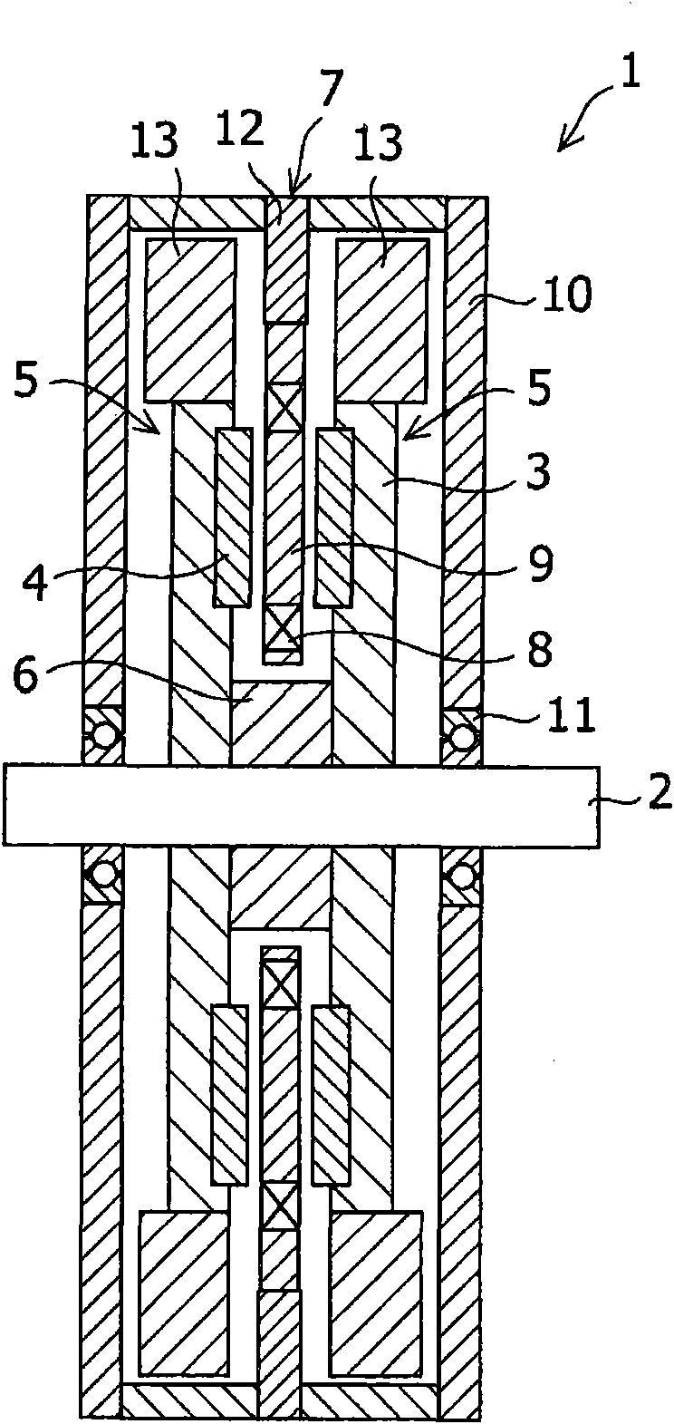
[0040] figure 1 The axial gap type rotary machine used in Example 1 is shown. Its material and size are similar to those of the comparative example, except that the material of the coil holder 9 is changed, a heat radiation fin 12 and a cooling fan 13 are added, and the housing 10 is extended in the radial direction.
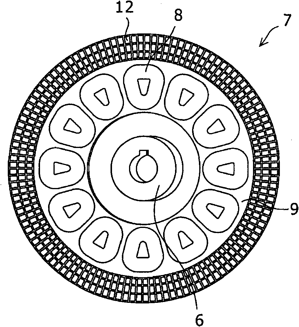
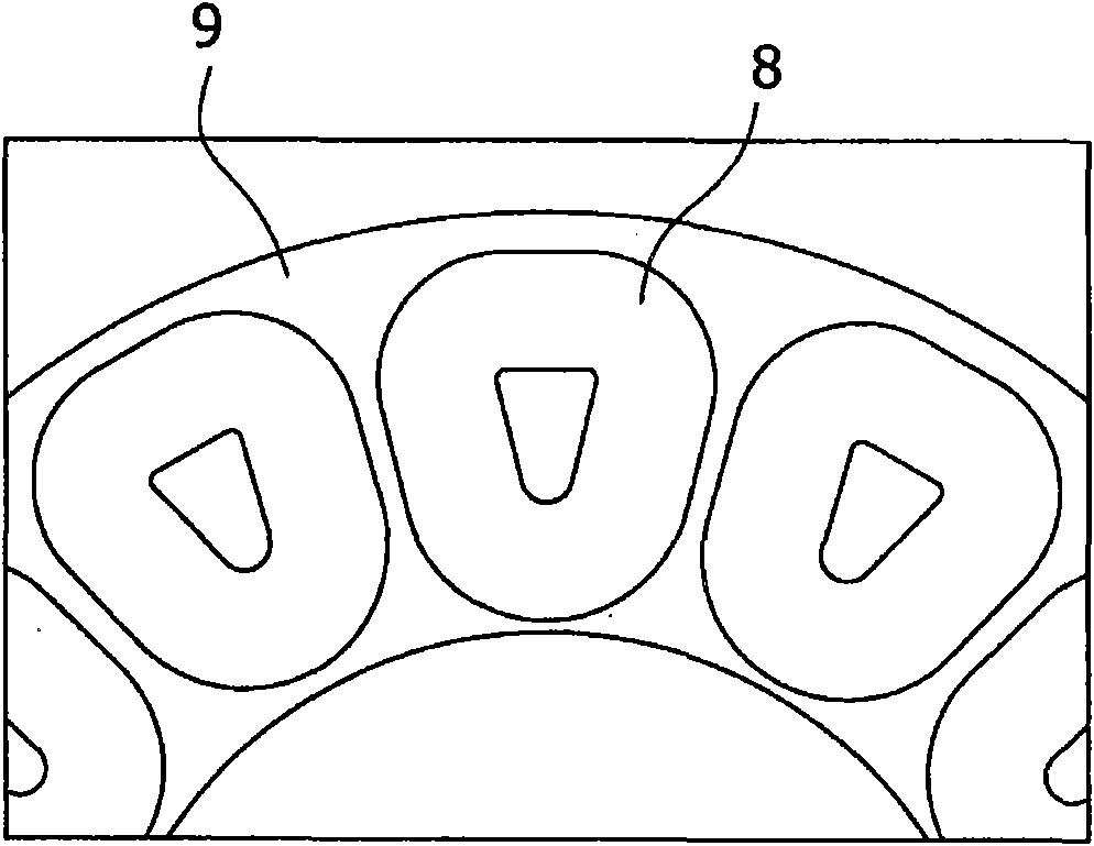
[0041] Coil holder 9 (thermal conductivity is 18W / mK, electrical conductivity is 0.12×10 -13 S / m) is made of thermoplastic resin (liquid crystal polymer) containing inorganic mineral particles composed of alumina. Such as figure 2 As shown, the coil 8 is dipped and formed. The heat radiation sheet 12 is made of aluminum (thermal conductivity 236W / mK), and is formed on its surface with a shape structural feature that increases its surface area by 3 times, thereby effectively applying the cooling effect from the cooling fan 13 to the coil holding Item 9 on. The cooling fans 13 are those manufactured by punching and then bending or welding them. Similar to ...
Embodiment 2
[0043] figure 2 The material of the coil holder 9 was changed, and the same test as in the above-mentioned embodiment 1 was carried out. The test conditions were similar to those when testing Example 1 except that the material of the coil holder 9 was changed. Through this test, the relationship between the thermal conductivity of the coil holder 9 and the coil temperature was obtained. Test results such as Figure 7 and shown in Table 1. Note that since there is no thermal conductivity of 40W / mK (conductivity: 1×10 5 S / m), therefore the test result values are not observations. Use the values obtained from the heat transfer analysis using the finite element method, and add.
[0044] Table 1
[0045] Thermal conductivity of coil holder (W / mK)
[0046] These results indicate that the increase in coil temperature is small when the thermal conductivity is not less than 5 W / mK, that is, good heat release can be secured within the range of thermal conductivity n...
PUM
 Abstract
Description
Claims
Application Information
 - R&D
- Intellectual Property
- Life Sciences
- Materials
- Tech Scout
- Unparalleled Data Quality
- Higher Quality Content
- 60% Fewer Hallucinations
Browse by: Latest US Patents, China's latest patents, Technical Efficacy Thesaurus, Application Domain, Technology Topic, Popular Technical Reports.
© 2025 PatSnap. All rights reserved.Legal|Privacy policy|Modern Slavery Act Transparency Statement|Sitemap|About US| Contact US: help@patsnap.com