Radiation generating apparatus and radiation imaging apparatus

A technology for generating device and radiation, which can be used in X-ray tubes, X-ray tubes, X-ray equipment, etc., and can solve problems such as low radiation efficiency

Inactive Publication Date: 2014-04-16
CANON KK
View PDF12 Cites 3 Cited by
  • Summary
  • Abstract
  • Description
  • Claims
  • Application Information

AI Technical Summary

Problems solved by technology

However, in general, the radiation generation efficiency is significantly low, and about 99% of the power consumption becomes heat

Method used


Image

  • Radiation generating apparatus and radiation imaging apparatus
  • Radiation generating apparatus and radiation imaging apparatus
  • Radiation generating apparatus and radiation imaging apparatus

Examples


Embodiment Construction

[0021] Hereinafter, embodiments of the present invention will be described with reference to the accompanying drawings.

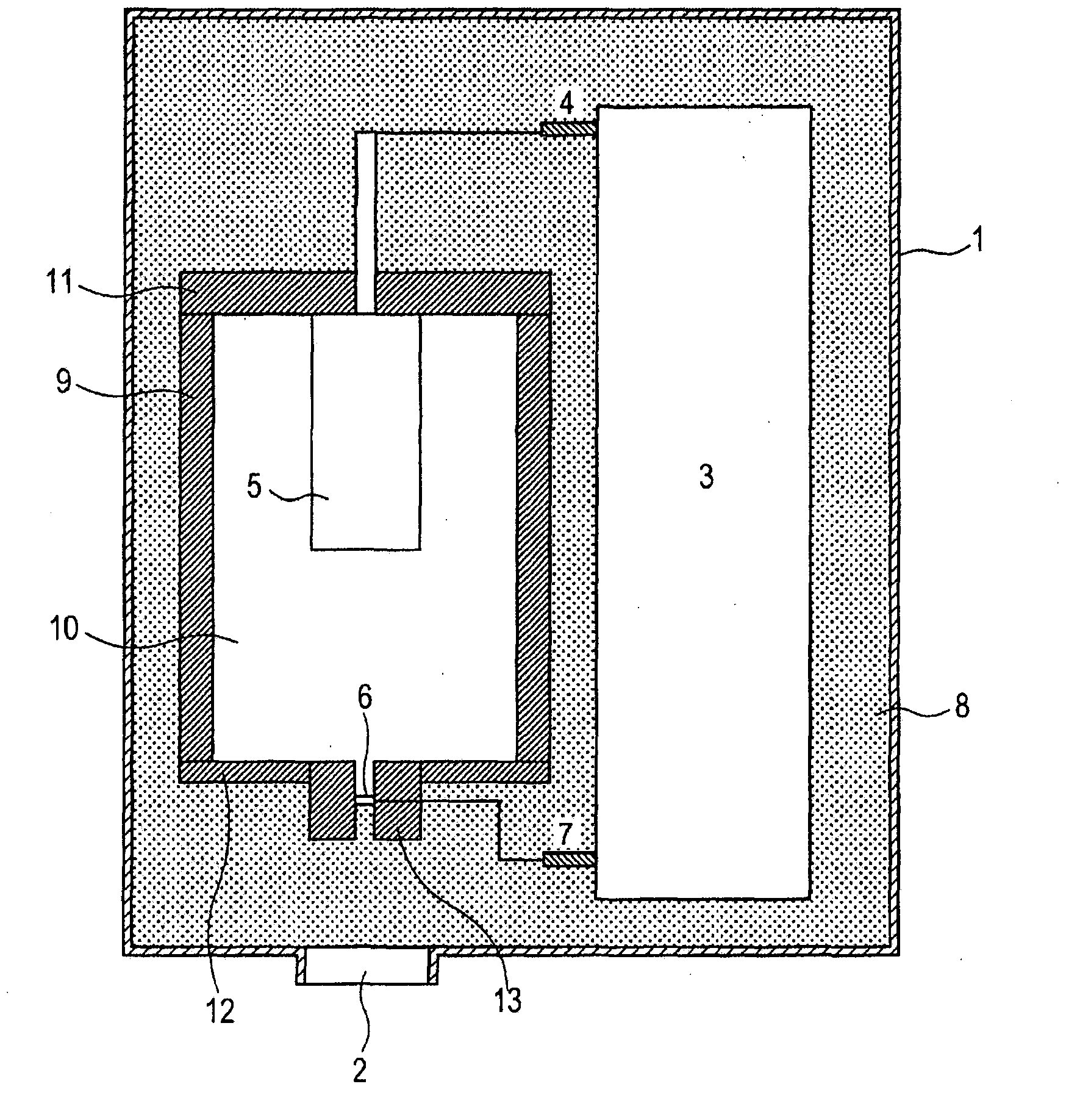
[0022] figure 1 is a schematic cross-sectional view illustrating one embodiment of the radiation generating device of the present invention. The outer package 1 accommodates a transmissive radiation tube 10 and a voltage control unit 3 (voltage control unit). The remaining space in the outer envelope 1 (between the inner wall of the outer envelope 1 and the radiation tube 10 ) is filled with an insulating fluid 8 .

[0023] The voltage control unit 3 includes a circuit board and an insulated transformer, and outputs a signal for controlling generation of radiation to the electron emission source 5 of the radiation tube 10 via a terminal 4 . Furthermore, this unit defines the voltage of the anode part 12 via the terminal 7 .

[0024] The outer capsule 1 may have sufficient strength to be used as a container, and be made of one of metal and plastic materia...


PUM


Abstract

A radiation generating apparatus of the present invention includes an envelope 1 including a first window 2 allowing radiation to pass; a radiation tube 10 that is accommodated in the envelope 1, and includes a second window 15 allowing radiation to pass, at a position opposite to the first window 2; a radiation passing hole 21 that is thermally connected to the second window 15 and communicates with the second window 15; and a radiation shielding member 16 protruding from the second window 15 toward the first window 2. In this apparatus, a thermal conducting member 17 having a higher thermal conductivity than the radiation shielding member 16 is connected to an outer periphery of the protruding portion of the radiation shielding member 16. The simple configuration can shield unnecessary radiation, and cool the target, while facilitating reduction in weight.

Description

technical field [0001] The present invention relates to a radiation generating device suitable for non-destructive X-ray imaging in the fields of medical devices and industrial devices and a radiation imaging device using the same. Background technique [0002] In general, a radiation tube accelerates electrons emitted from an electron emission source by a high voltage, and irradiates a target, thereby generating radiation such as X-rays. Radiation rays generated at this time are emitted in all directions. PTL 1 discloses a transmission X-ray generating device including X-ray shielding members disposed on an electron incident side and an X-ray emitting side with respect to an object for shielding unnecessary X-rays. [0003] A high voltage needs to be applied between an electron emission source and a target in order to irradiate the target with a high-energy electron beam to generate radiation suitable for radiographic imaging. However, in general, radiation generation eff...

Claims


Application Information

Patent Timeline
Patent Type & Authority Applications(China)
IPC IPC(8): H05G1/02H05G1/04
CPCH05G1/04H01J35/12H01J2235/122H05G1/025H01J2235/186H01J2235/166H01J35/16H01J35/13H01J35/186G01N23/04
Inventor 柳沢芳浩上田和幸野村一郎田村美树青木修司三道和宏
Owner CANON KK
Why Eureka
Try Eureka