Cutting tool
A technology of cutting tools and substrates, applied in the direction of manufacturing tools, turning equipment, metal processing equipment, etc., can solve the problem of insufficient wear resistance and defect resistance of the coating, insufficient defect resistance of the coating, insufficient cutting performance, etc. question
- Summary
- Abstract
- Description
- Claims
- Application Information
AI Technical Summary
Problems solved by technology
Method used
Image
Examples
no. 2 Embodiment approach
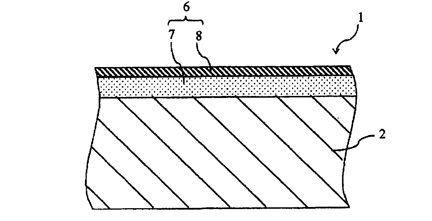
[0066] As a second example of the substrate 2, Al 2 o 3 The particles contain 0 to 1% by mass of MgO, a total of 10 to 70% by mass of at least one selected from the group of carbides, nitrides, and carbonitrides of Ti or Si, and a total of 0.1 to 2.0% by mass % of Al selected from at least one of Co and Ni 2 o 3quality ceramics. Here, by including Ti or Si carbides, nitrides, and carbonitrides in the ceramics, the strength and toughness of the base can be improved, and the adhesion to the coating layer 6 of the present invention can also be improved. In addition, the content of any one or more selected from Ti or Si carbides, nitrides, and carbonitrides is preferably 20 to 40% by mass from the viewpoint of eliminating the difference in thermal expansion coefficient with the coating layer 6. Make Al 2 o 3 It is particularly preferable to contain TiC or TiCN in an amount of 20 to 40% by mass from the viewpoint that the high-quality ceramics have conductivity and film forma...
Embodiment 1
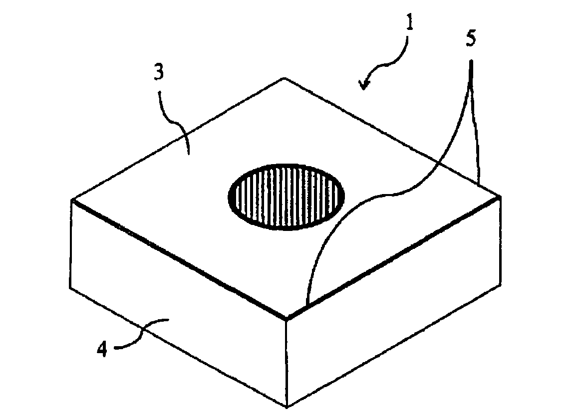
[0110] Using tungsten carbide (WC) powder with an average particle size of 0.8 μm as the main component, 10% by mass of metal cobalt (Co) powder with an average particle size of 1.2 μm and 0.1% by mass of vanadium carbide ( VC) powder, 0.3% by mass of chromium carbide (Cr 3 C 2 ) powder, mixed, formed into CNMG120408MS-shaped multi-edged cutter head shape by press molding, and then subjected to binder removal treatment, followed by firing in a vacuum of 0.01Pa at 1450°C for 1 hour to produce super hard alloy. In addition, grinding processing was performed by blasting, brushing, or the like on the rake face surface of each sample. Furthermore, the obtained cemented carbide is subjected to edge treatment (honing) by brushing.
[0111] For the substrate prepared as described above, the first target for forming the first layer and the second target for forming the second layer shown in Table 1 were arranged on opposite sides of the film forming apparatus. First, use the first ...
Embodiment 2
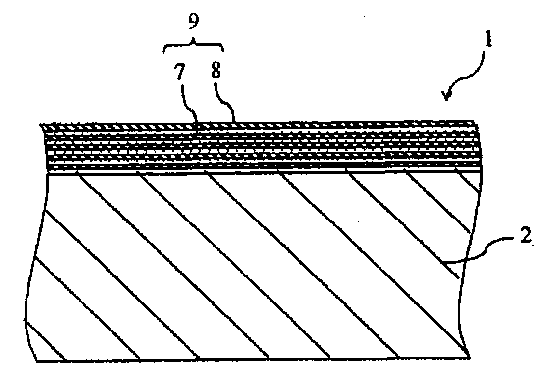
[0133] Opposed to the cover layer of Example 1, the first target for forming the first layer and the second target for forming the second layer shown in Table 4 were arranged opposite to the film forming apparatus. According to the film formation conditions in Table 4, the sample stage installed in the device was rotated while generating plasma from the two targets, and the first layer was alternately laminated at the period of the thickness shown in Table 5. Except for the coating layer having the configuration of the second layer, a cutting tool was produced in the same manner as in Example 1, and the cutting performance was evaluated in the same manner (I-15 to 28). The results are shown in Table 5.
[0134] [Table 4]
[0135]
[0136] The * mark represents a sample outside the scope of the present invention.
[0137] [table 5]
[0138]
[0139] The * mark represents a sample outside the scope of the present invention.
[0140] As can be seen from the results show...
PUM
| Property | Measurement | Unit |
|---|---|---|
| thickness | aaaaa | aaaaa |
| particle diameter | aaaaa | aaaaa |
| particle diameter | aaaaa | aaaaa |
Abstract
Description
Claims
Application Information
 - R&D
- Intellectual Property
- Life Sciences
- Materials
- Tech Scout
- Unparalleled Data Quality
- Higher Quality Content
- 60% Fewer Hallucinations
Browse by: Latest US Patents, China's latest patents, Technical Efficacy Thesaurus, Application Domain, Technology Topic, Popular Technical Reports.
© 2025 PatSnap. All rights reserved.Legal|Privacy policy|Modern Slavery Act Transparency Statement|Sitemap|About US| Contact US: help@patsnap.com


