
Injection moulding-based high-efficiency heavy-duty transmission nut material, method and device

A transmission nut and nut technology, applied in the coating and other directions, can solve the problems of complex lining production process, hindering the application in heavy-duty fields, bearing capacity limitation, etc., and achieve the effect of improving equipment efficiency, ingenious design, and effective lubricating oil passages.

Inactive Publication Date: 2010-07-14
GUANGDONG UNIV OF TECH
View PDF0 Cites 8 Cited by
  • Summary
  • Abstract
  • Description
  • Claims
  • Application Information

AI Technical Summary

Problems solved by technology

Although nuts using non-metallic materials have achieved great results in reducing friction loss and improving transmission efficiency, due to the nut's non-metallic overall structure, the load-carrying capacity is greatly limited, which hinders its application in heavy-duty fields.
[0004] Steel-backed carbon fiber fabric reinforced self-lubricating composite nuts have both high load capacity and good friction performance, but due to the need to use carbon fiber fabric (fiber cloth) for reinforcement, manual coating, and complicated lining manufacturing process, it hinders its popularization and application

Method used


Image

  • Injection moulding-based high-efficiency heavy-duty transmission nut material, method and device
  • Injection moulding-based high-efficiency heavy-duty transmission nut material, method and device
  • Injection moulding-based high-efficiency heavy-duty transmission nut material, method and device

Examples


Embodiment 1

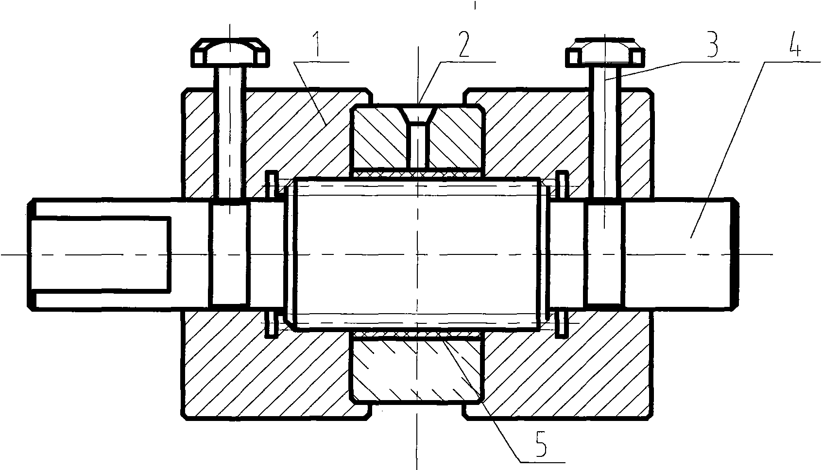
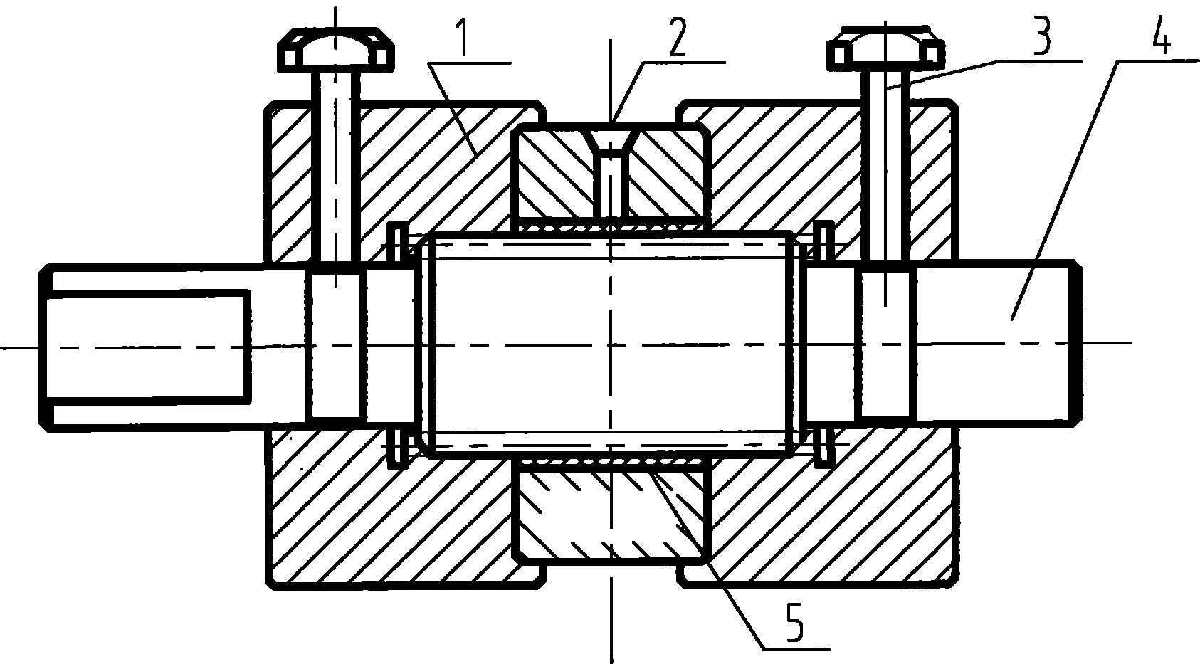
[0025] The structural representation of the self-lubricating transmission nut forming device of the present invention is as follows figure 1 As shown, it includes a process screw 4, a base nut 2, a positioning member 1, and a tightening member 3, wherein the process screw 4 is screwed into the transmission nut 2, and the internal thread of the base nut 2 is connected to the surface of the external thread of the process screw 4. A gap is reserved between which self-lubricating material can be injected to form a self-lubricating lining 5 , and the two ends of the base nut 2 are provided with a positioning member 1 , and the positioning member 1 is locked by a tightening member 3 .

[0026] A gap of 1 mm to 2 mm is reserved between the internal thread of the base nut 2 and the surface of the external thread of the process screw 4 . In this embodiment, a gap of 1 mm is reserved between the internal thread of the base nut 2 and the surface of the external thread of the process scre...

Embodiment 2

[0038] The method and device of this embodiment are the same as those of Embodiment 1, except that the proportioning of the lining material is different. The proportioning of the lining material in this embodiment is as follows:

[0039] Epoxy resin 40 Toughening agent, dispersant 6 Talcum powder 400 mesh 8

[0040] Graphite 2 Molybdenum Disulfide 15 Carbon Fiber 10 Curing Agent 19.

Embodiment 3

[0042] The method and device of this embodiment are the same as those of Embodiment 1, except that the proportioning of the lining material is different. The proportioning of the lining material in this embodiment is as follows:

[0043] Epoxy resin 45 toughening agent, dispersant 8 talcum powder 400 mesh 5

[0044] Graphite 3 Molybdenum Disulfide 10 Carbon Fiber 14 Curing Agent 15.0.


PUM

PropertyMeasurementUnit
lengthaaaaaaaaaa
diameteraaaaaaaaaa
thicknessaaaaaaaaaa

Abstract

The invention discloses a carbon fiber-reinforced self-lubricating composite material and a method and a device for manufacturing steel backing self-lubricating composite material transmission nuts through injection moulding of the material. The self-lubricating composite material consists of epoxy resin, carbon fiber and various fillers and modified substances. The composite material forms a self-lubricating lining on the surface of a steel nut substrate in an injection moulding mode. The injection moulding device comprises a substrate nut (2), a process screw rod (4) screwed into the substrate nut (2), and two positioning nuts (1). A gap between 1 and 2mm is reserved between the substrate nut (2) and the process screw rod (4) and is uniformly distributed in the axial direction, the peripheral direction and the radial direction. Before the injection, a lubricating oil way with proper thickness is formed by adhereing an adhesive tape or drawing through paraffin on the surface of the process screw rod (4); the composite material is injected into the injection moulding device through a charging barrel; and after the injection is finished and the lining is completely cured, the positioning nuts (1) are disassembled, the transmission nut (2) manufactured is screwed out of the process crew rod (4), residues in the lubricating oil way are removed, and the required transmission nut (2) is obtained. The novel nut has the advantages of high bearing capacity, small friction coefficient and good dynamic performance.

Description

technical field [0001] The invention relates to a carbon fiber reinforced self-lubricating composite material and a method and device for manufacturing a steel-backed self-lubricating composite transmission nut by injection molding the material, which belongs to the innovative technology of screw transmission. Background technique [0002] Screw transmission is an important mechanical transmission method, which can convert the rotary motion of the prime mover into linear motion, and is widely used in various mechanical equipment. The common screw transmission pair has three forms: sliding, rolling and static pressure screw. The sliding screw transmission pair is the most common transmission form, which has the advantages of simple structure and low price. However, under the condition of low speed and heavy load, the contact helical surface is often in a state of boundary lubrication, the nut wears seriously, the friction coefficient is high, and the transmission efficiency ...

Claims


Application Information

Patent Timeline
Patent Type & Authority Applications(China)
IPC IPC(8): C08L63/00C08K13/04C08K7/06C08K3/34C08K3/04C08K3/30B29C45/00
Inventor 孙友松王万顺李春梅魏良模程永奇董智贤
Owner GUANGDONG UNIV OF TECH
Learn More