Quasi-molecule lamp apparatus

An excimer lamp and lamp housing technology, which is applied to lighting devices, cooling/heating devices of lighting devices, discharge lamps, etc., can solve the problems of inert gas retention, temperature rise and decrease of luminous gas, etc., and achieve easy shrinkage and ease warping. the effect of the song

Active Publication Date: 2014-07-23
USHIO DENKI KK
View PDF6 Cites 0 Cited by
  • Summary
  • Abstract
  • Description
  • Claims
  • Application Information

AI Technical Summary

Problems solved by technology

[0006] However, when the temperature of the light-emitting gas enclosed in the discharge vessel of the excimer lamp rises, the generation of excimers is hindered and the amount of light emitted decreases.
When the input power of the excimer lamp is increased, the temperature of the luminous gas inside will rise, so there is a problem that even if the input is increased to increase the illuminance, the luminous efficiency will decrease
In order to send out the gas with a fast flow rate without changing the total flow rate, it is necessary to reduce the diameter of the discharge port or reduce the number of discharge ports. Therefore, stagnation of inert gas will occur between the discharge ports formed on the gas supply pipe.
[0010] In addition, in order to improve the efficiency of substrate surface treatment, the inert gas must be continuously replaced in the lamp housing, and the method of installing nozzles for cooling under the lamp or on the side of the same height will hinder the replacement of the inert gas. Unable to adopt

Method used


Image

  • Quasi-molecule lamp apparatus
  • Quasi-molecule lamp apparatus
  • Quasi-molecule lamp apparatus

Examples


Embodiment Construction

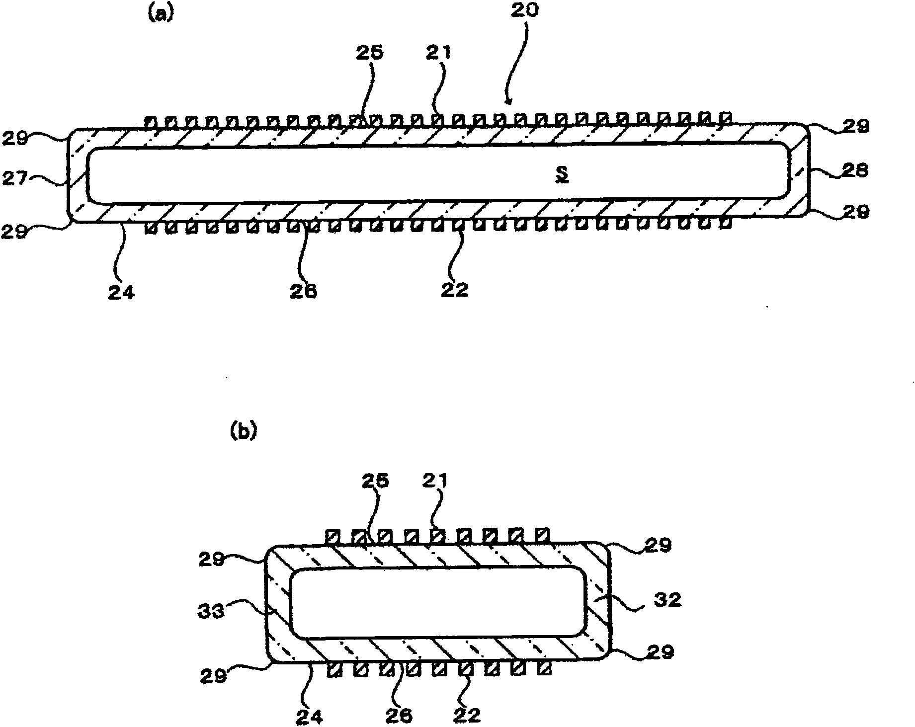
[0036] figure 1 (a) and figure 1 (b) is a schematic configuration diagram of an example of the excimer lamp 20 provided in the excimer lamp device of the present invention, figure 1 (a) is a cross-sectional view along the length direction, figure 1 (b) is a cross-sectional view along the width direction.

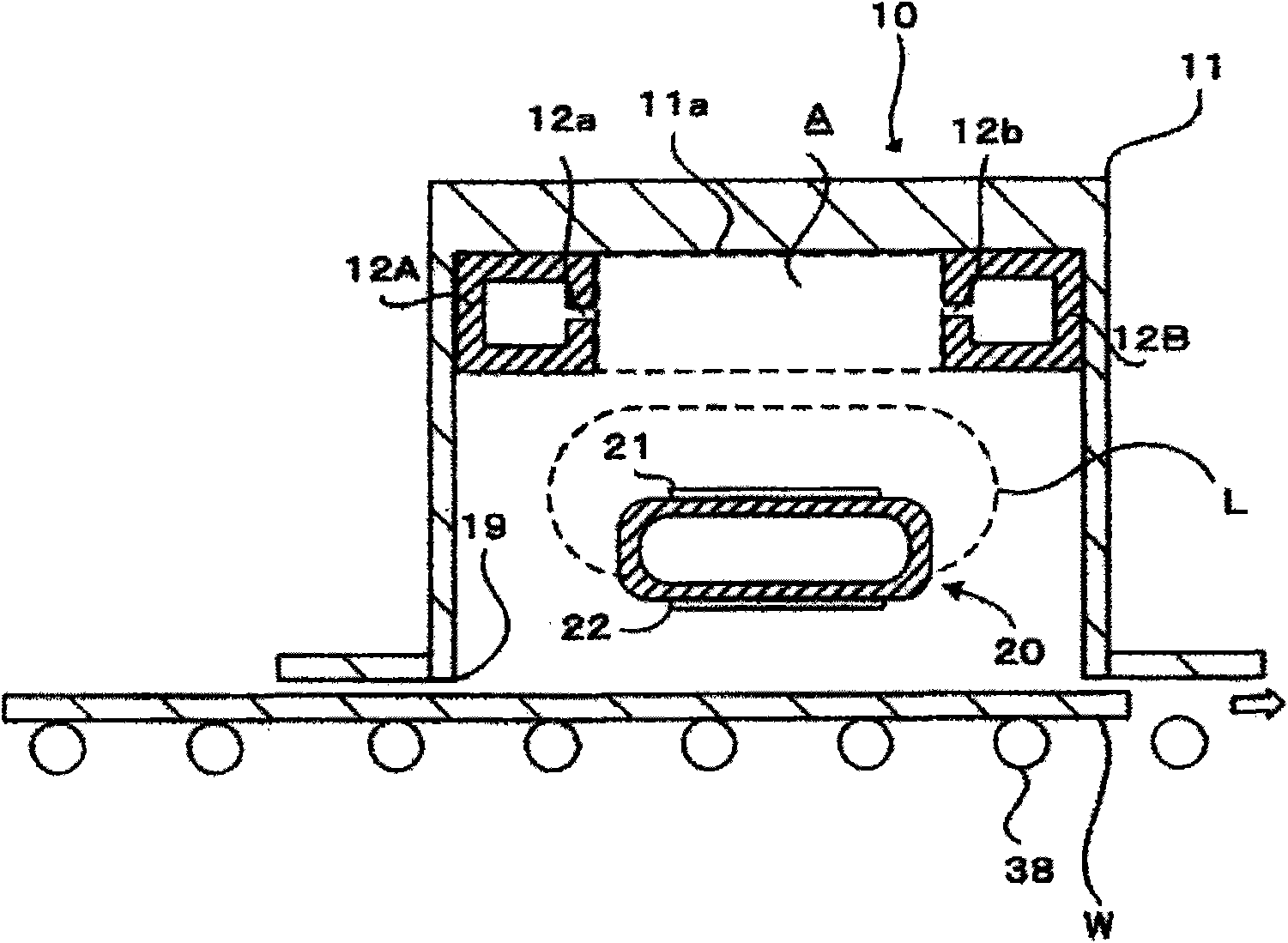
[0037] Such as figure 2 As shown, the excimer lamp 20 is made of silica glass as a dielectric material, and has a flat square tube-shaped discharge vessel 24 with rounded four corners. The discharge space S formed inside the discharge vessel 24 is filled with, for example, a rare gas such as xenon gas or a gas mixed with a halogen gas such as chlorine gas as the discharge gas. Excimer light of different wavelengths is generated depending on the type of discharge gas. The discharge gas is usually filled with a pressure of about 10 to 100 KPa.

[0038]In the discharge vessel 24, a flat wall 25 on the upper side and a flat wall 26 on the lower side are separated from...


PUM


Abstract

The invention provides an excimer lamp device. Inert gas is evenly disposed inside a lamp housing to improve surface treatment efficiency and the lamp is cooled down to improve the emitting efficiency of vacuum ultraviolet. The invention is the excimer lamp device irradiating the conveyed object to be treated and comprising a lamp housing (10) at an opening set below vertically, an excimer lamp (20) inside the lamp housing (10), an air supply tube (12A) with an air outlet (12a) and a convey mechanism (38). A plurality of air supply tubes (12A) is separately located inside the lamp housing (10) and the adjacent air supply tubes (12A) has at least a pair of air outlets. The air outlet (12a) set at the air supply tubes (12A) and the air outlet (12b) set at the air supply tube (12B) are in the pair relationship. As to the pair of the air outlets, the outlet directions of the air outlet (12a) and the air outlet (12b) are in opposition or crossing over each other in the space (A) defined by the adjacent air supply tubes. The excimer lamp is disposed more below the space (A) defined by the adjacent air supply tubes.

Description

technical field [0001] The invention relates to an excimer lamp device. In particular, it relates to an excimer lamp device used for cleaning of a semiconductor substrate or a liquid crystal substrate in a manufacturing process of a semiconductor substrate or a liquid crystal substrate. Background technique [0002] In recent years, in the manufacturing process of semiconductor substrates or liquid crystal substrates, as a method of removing dirt such as organic compounds adhering to the surface of a wafer as a semiconductor substrate or a glass substrate as a liquid crystal substrate, ultraviolet light is widely used. Dry cleaning method. In particular, in the cleaning method by ozone or active oxygen using vacuum ultraviolet rays radiated from an excimer lamp, various cleaning devices that perform cleaning more efficiently and in a short time are proposed, for example, Patent Document 1 is known. [0003] Figure 14 It shows the same structure as the conventional excimer...

Claims


Application Information

Patent Timeline
Patent Type & Authority Patents(China)
IPC IPC(8): H01J65/00H01J61/35F21V29/02H01L21/304B08B5/02B08B7/00
CPCH01L21/67028
Inventor 远藤真一
Owner USHIO DENKI KK
Why Eureka
Try Eureka