


Quick Research
Generate reliable direction feasibility study reports for your R&D in just a few steps.

Technical Q&A
Discover and master advanced knowledge NOW. Basics, ideas, possibilities, all at once.

Find Solutions
As an expert in R&D theories, this can generate solutions to your technical problems instantly.

Evaluate Feasibility
Analyze your overall solution with one click, know your potential R&D risks in advance.

Monitor Landscape
Get weekly tech updates, stay abreast of the latest tech innovations and key insights.
Metal microfiber-nano carbon composite material and preparation method
A composite material and metal microfiber technology, applied in the field of materials, can solve the problems of unfavorable electric double layers, high impedance, limited carbon nanotube carrying capacity, etc., and achieve the effects of broad application prospects, low manufacturing costs, and easy manufacturing.
- Summary
- Abstract
- Description
- Claims
- Application Information
AI Technical Summary
Problems solved by technology
Method used
Image

Examples
preparation example Construction
[0027] The first is the preparation of monolithic sintered metal microfiber matrix
[0028] Using papermaking / post-sintering technology to prepare a sintered metal microfiber structure matrix with a large porosity and a three-dimensional network structure, the specific preparation process refers to the literature (Appl.Catal.A2007, 328:77; AIChEJ2007, 53:1845); metal fiber They are: 8 micron diameter Ni fiber, 12 micron stainless steel (alloy, SS-316L) fiber, 8 micron diameter Cu fiber, 8 micron diameter Co fiber, 8 micron diameter Fe fiber and 8 micron diameter Al fiber ; The sintering process for preparing the overall large-area microfiber structure is carried out in a hydrogen atmosphere, and the sintering temperatures are: 950°C, 1100°C, 900°C, 950°C, 1000°C and 650°C.
[0029] The obtained monolithic sintered metal microfiber matrix is respectively expressed as: SF Ni , SF SS , SF Cu , SF Co , SF Fe and SF Al The thickness of the sintered metal microfiber matrix i...
Embodiment 1-3
[0032] Cut the sintered Ni metal microfiber matrix SF with a diameter of 8.5 cm Ni , as for the quartz tube reactor with an inner diameter of 8.5 cm, purging with high-purity nitrogen at room temperature to fully replace the air; 300ml / min; at 700°C, ethylene in SF Ni Decompose under the catalytic action of Ni metal microfiber substrate and deposit carbon on the surface of the Ni metal microfiber matrix; control the time of feeding ethylene / hydrogen mixed gas to 2 minutes, 30 minutes and 60 minutes respectively, and then switch to high-purity nitrogen to fully purge and in nitrogen atmosphere The nano-carbon-Ni metal microfiber composites were prepared by cooling down to room temperature, which were denoted as NC-SF Ni -1, NC-SF Ni -2 and NC-SF Ni -3, the amount of carbon deposition was 1% by weight, 52% by weight and 62% by weight, respectively.
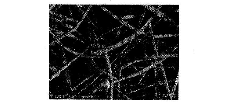
[0033] NC-SF Ni The optical, scanning electron microscope (SEM) and transmission electron microscope (TEM) diagrams of -2 ref...
Embodiment 4-8
[0035] Except for the following differences, other conditions are the same as in Example 2.
[0036] Replace ethylene with carbon monoxide, methane, ethane, propane and butane respectively; when using methane as the carbon source, control the reaction temperature at 750°C; when using propane and butane as the carbon source, the gas flow rate is 50 ml / min .
[0037] The prepared nano-carbon-Ni metal microfiber composites are denoted as NC-SF Ni -4, NC-SF Ni -5, NC-SF Ni -6, NC-SF Ni -7 and NC-SF Ni -8, the carbon deposition amounts thereof were 35% by weight, 44% by weight, 49% by weight, 52% by weight and 56% by weight.
[0038] NC-SF Ni The transmission electron microscope (TEM) picture of -5 is referred to Image 6 ,Depend on Image 6 It can be seen that there are both carbon nanotubes and amorphous carbon.
PUM
| Property | Measurement | Unit |
|---|---|---|
| diameter | aaaaa | aaaaa |
| voidage | aaaaa | aaaaa |
| diameter | aaaaa | aaaaa |
Abstract
Description
Claims
Application Information
 - R&D Engineer
- R&D Manager
- IP Professional
- Industry Leading Data Capabilities
- Powerful AI technology
- Patent DNA Extraction
Browse by: Latest US Patents, China's latest patents, Technical Efficacy Thesaurus, Application Domain, Technology Topic, Popular Technical Reports.
© 2024 PatSnap. All rights reserved.Legal|Privacy policy|Modern Slavery Act Transparency Statement|Sitemap|About US| Contact US: help@patsnap.com