
Production method of ball valve core

A manufacturing method and a valve core technology, which are applied to valve devices, cocks including cutting devices, engine components, etc., can solve the problems of unreliable processing technology, thick metal pipes, and high defective rate, and achieve material saving, strength improvement, The effect of high yield

Inactive Publication Date: 2009-02-11
黄勇
View PDF1 Cites 20 Cited by
  • Summary
  • Abstract
  • Description
  • Claims
  • Application Information

AI Technical Summary

Problems solved by technology

Although the ball valve spool produced by the above method is better in water resistance and sealing than the ball valve spool produced by foundry casting, and saves materials; For circular seam welding, it is necessary to ensure that the pipe wall will not be broken down by the current and the welding itself must have enough padding material, so the metal pipe material used for the inner straight pipe is thicker, and the cost is relatively high; after welding, because the welding point is just on the sealing surface, Using this method, after the product is processed, defects such as virtual welding, air holes, and insufficient fillers are found to form depressions. Since there is no machining allowance on the surface, it cannot be remedied, so the processing technology is extremely unreliable and the defective rate is high.

Method used


Image

  • Production method of ball valve core
  • Production method of ball valve core
  • Production method of ball valve core

Examples


Embodiment 1

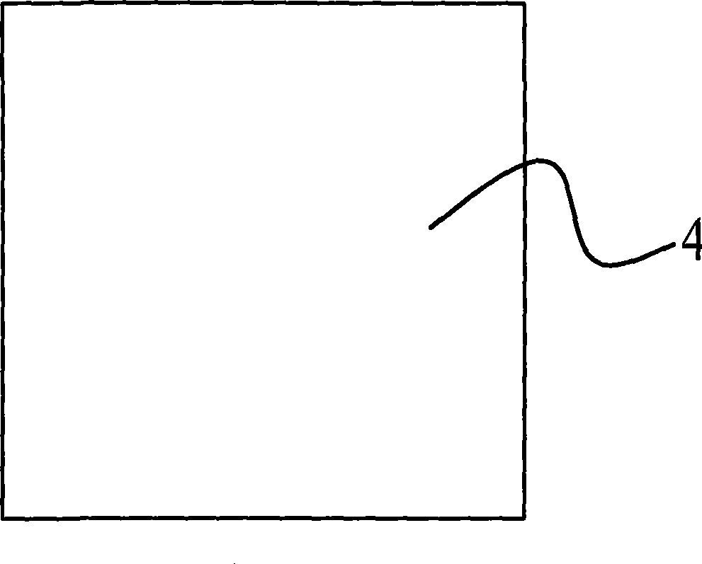
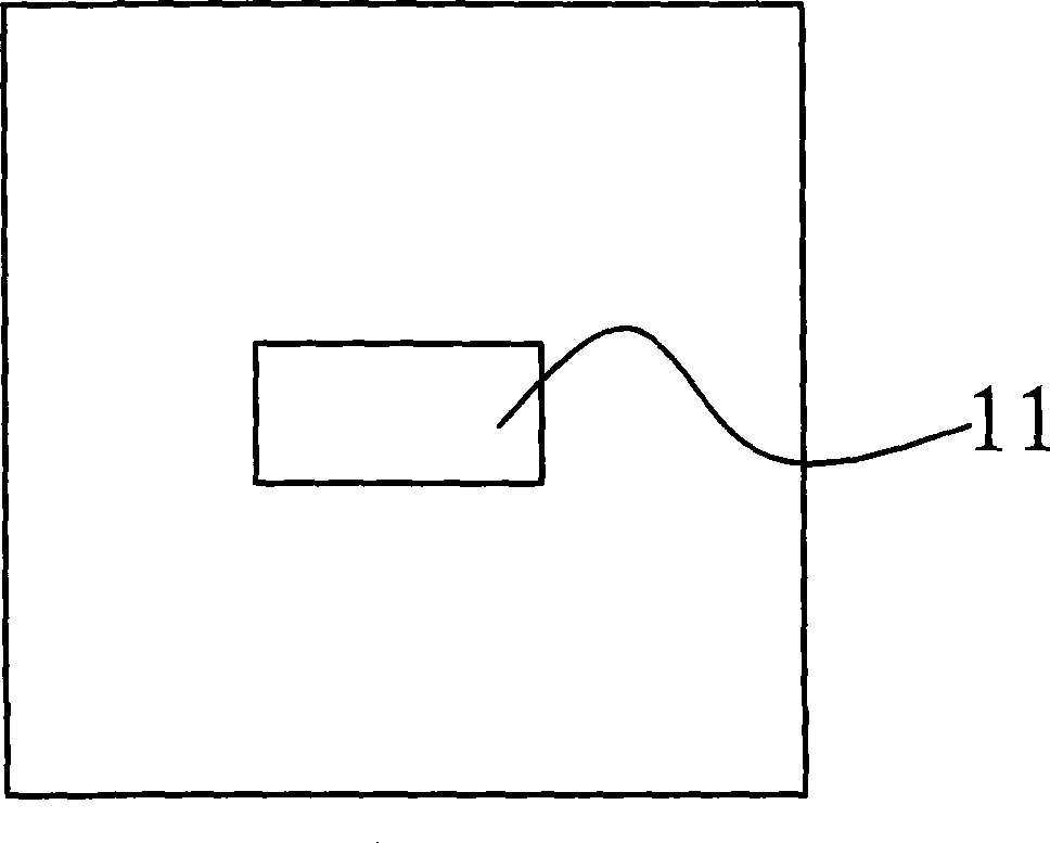
[0034] In the manufacture method of this ball valve spool, the metal plate 4 of the outer spherical shell 1 that selects to make the ball valve spool 1 of the present invention is stainless steel plate 4, and the thickness of stainless steel plate is about 1mm~1.5mm, according to the size of ball valve spool with cutting machine Cut it to the required length and its structure diagram is as follows figure 1 As shown, the installation hole 11 is punched out by a punching machine in the middle of the stainless steel plate, and its structural schematic diagram is shown in figure 2 shown.

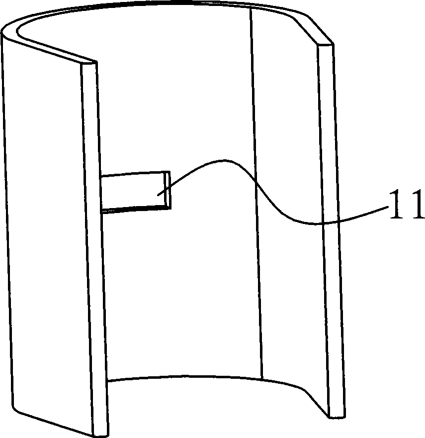
[0035] Select a suitable mold for making the metal round tube 5, put the stainless steel plate on the mold to bend it into a U shape, and then use a punch or punching machine on the mold to punch the U-shaped plate into a stainless steel round tube 5. Its structural diagram is as follows image 3 and Figure 4Shown; weld the pipe seam of the stainless steel round pipe 5 with a welding machine...

Embodiment 2

[0041] The selected stainless steel plate 4 did not punch out the installation hole 11 through a punching machine, and did not make the valve stem connecting seat 2 separately, but cut a straight seam with a saw blade milling cutter at the middle position of the two through holes of the outer spherical shell blank, and then used a deformation mold to cut a straight seam. Stamping makes valve stem groove 21, and it matches with the valve stem of ball valve. Other manufacturing processes are the same as in Embodiment 1, and will not be described in detail.


PUM

PropertyMeasurementUnit
thicknessaaaaaaaaaa
thicknessaaaaaaaaaa

Abstract

The invention provides a method for producing the core of a ball valve, which belongs to the technical field of valve production, and solves the problems of a large amount of material, high cost and high defective rate in the prior art. The production method of the core of the ball valve is realized through the following steps: firstly, an outer ball shell is produced; secondly, an inner straight pipe is installed; and thirdly, surface treatment is carried out. Through the production method, the material is greatly saved, and the cost for the core of the ball valve is reduced; the precision, the thickness and the integrity of the produced core of the ball valve can be guaranteed, and the intensity of the valve handle connecting seat and the valve handle connecting part is enhanced; the reliability of the production method is good, and the rate of finished products is high; the technological process of the production method is simplified, the appearance of the produced core of the ball valve is beautiful, and the core is comparatively perfect; if stainless steel material is selected to produce the core of the ball valve, galvanization is not needed, therefore, the environment protection property is good.

Description

technical field [0001] The invention relates to a method for manufacturing a valve core, in particular to a method for manufacturing a ball valve core, and belongs to the technical field of valve manufacturing. Background technique [0002] Valves are widely used in modern society. Especially in the technical field of plumbing pipe fittings, there are many kinds of valves in the prior art, mainly ball valves, angle valves, globe valves, etc., wherein the structure of the ball valve is relatively simple, mainly because the spool of the ball valve is relatively simple. The spool of the ball valve has a symmetrical spherical structure as a whole, with a cylindrical through hole in the middle, and a stem groove connected to the valve stem at the center of the outer spherical surface of the spool. When working, it rotates The valve stem aligns the cylindrical through hole of the spool with the inlet and outlet of the ball valve, and when it stops working, reversely turns the val...

Claims


Application Information

Patent Timeline
Patent Type & Authority Applications(China)
IPC IPC(8): B23P15/00F16K5/06
Inventor 黄勇
Owner 黄勇
Learn More