
Cavity electrode

An electrode and cavity technology, applied in the field of medical devices, to simplify the production process, eliminate false welding failures, and reduce the rate of defective products

Active Publication Date: 2015-12-16
福州仁馨医疗科技有限公司
View PDF8 Cites 1 Cited by
  • Summary
  • Abstract
  • Description
  • Claims
  • Application Information

AI Technical Summary

Problems solved by technology

[0004] In the prior art, the cavity electrodes drawn out by connecting wires and metal electrodes after welding conduction, although their conductivity is low, still need welding process and connecting wire parts, which can further reduce material cost, production cost and defective rate, The need to avoid environmental pollution and reduce resource consumption

Method used


Image

  • Cavity electrode
  • Cavity electrode
  • Cavity electrode

Examples


Embodiment Construction

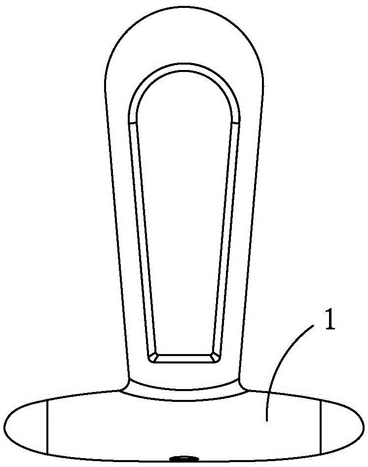
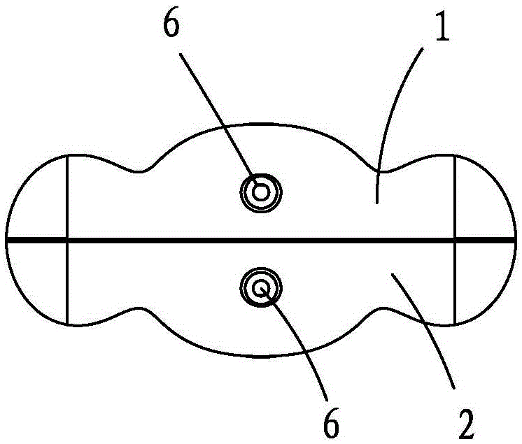
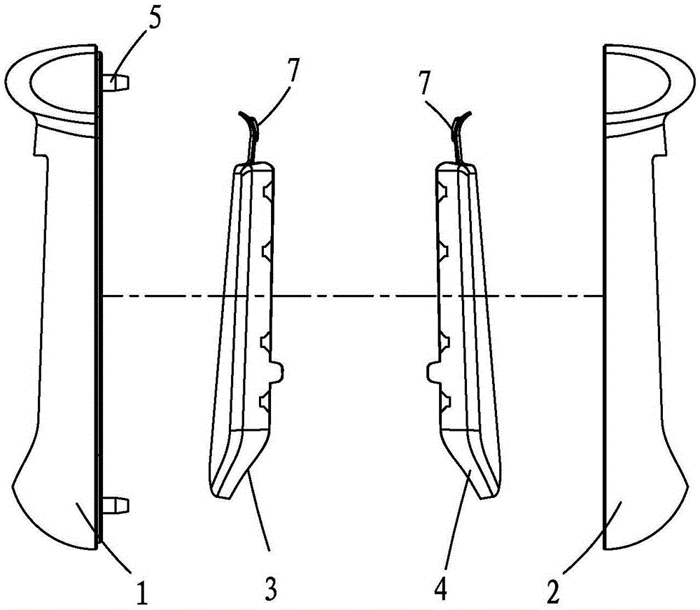
[0019] Please also see Figure 1 to Figure 4 As shown, a channel electrode includes an upper shell 1 and a lower shell 2 made of plastic thermoplastic molding, an upper electrode 3 and a lower electrode 4 made of conductive materials; the upper electrode 3 and the lower electrode The conductive material of 4 is made of stainless steel sheet stamping and forming; the upper shell 1 and the lower shell 2 are fixed and assembled into a hollow T-shaped structure with a smooth arc surface at the front end through the positioning device 5; the upper electrode 3 and the lower electrode 4 are respectively embedded in the upper case 1 and the lower case 2, and part of the surface is exposed through the windows of the upper case 1 and the lower case 2 to achieve the purpose of contacting the cavity. 1 and the end faces of the lower housing 2 are respectively provided with through holes 6, and the tail end faces of the upper electrode 3 and the lower electrode 4 are provided with bosses 7...


PUM


Abstract

A cavity electrode comprises an upper casing, a lower casing, an upper electrode and a lower electrode, wherein the upper casing and the lower casing are made of an insulating material and provided with windows; and the upper electrode and the lower electrode are made of a conductive material. The conductive material of the upper electrode and the lower electrode is made of metal parts. The upper casing and the lower casing are fixedly assembled into a hollow geometry structure through a locating device. The upper electrode and the lower electrode are embedded in the upper casing and the lower casing respectively, and part of surfaces of the upper electrode and the lower electrode are exposed through the windows of the upper casing and the lower casing. Through holes are formed in the end faces of tail ends of the upper casing and the lower casing respectively, the end faces of tail ends of the upper electrode and the lower electrode are provided with bosses, a conductive connecting device connected with a signal line of a test instrument is inserted in the through holes, penetrates a locating hole of the locating device, and abuts against the bosses to form elastic deformation close fit. The conductive performance of the cavity electrode is greatly improved, the manufacturing cost is low, and the working reliability is high.

Description

【Technical field】 [0001] The invention belongs to a medical device, in particular to a low-resistance cavity electrode capable of collecting and transmitting electrophysiological signals. 【Background technique】 [0002] The pelvic floor muscles are like a hanging net, tightly hanging the urethra, bladder, vagina, uterus, rectum and other organs, so as to maintain their normal positions so that they can perform their functions. Pelvic floor muscles are closely related to urinary control, urination, defecation, and sexual life. Dysfunction of pelvic floor muscles may lead to pelvic floor organ prolapse, urinary incontinence, fecal incontinence, constipation, pelvic floor pain, sexual dysfunction, etc. disease. The use of electrophysiological methods to screen, evaluate or treat the functional status of the pelvic floor muscles has important clinical significance. This requires the use of a cavity electrode inserted into the vagina or rectum to cooperate with the diagnosis an...

Claims


Application Information

Patent Timeline
Patent Type & Authority Applications(China)
IPC IPC(8): A61B5/0492A61N1/05A61B5/296
Inventor 宋岩峰沈平
Owner 福州仁馨医疗科技有限公司
Learn More