Copper bar connection device between UPS circuit boards

A technology for connecting devices and circuit boards, applied in the directions of circuits, connections, fixed connections, etc., can solve the problems of short-circuiting of the insulation layer of the wires, high processing costs of copper columns, and it is not easy to prevent fool-proof design, achieve good contact, save raw materials, The effect of stable connection

Pending Publication Date: 2018-09-21
BAINADE CHINA YANGZHOU
View PDF0 Cites 1 Cited by
  • Summary
  • Abstract
  • Description
  • Claims
  • Application Information

AI Technical Summary

Problems solved by technology

Hard-connected copper columns and copper bars need to be designed and customized, which is costly, but they are safe and easy to install; copper columns and copper bars require high precision during design and installation, and rigid copper columns and copper bars It will cause stress on the circuit board, and pulling the circuit board will cause the circuit board to deform or even break; the thread on the copper post for installation is easy to slip; the processing cost of the copper post is relatively high
[0004] The cost of soft connection is low and the design is simple, but because the wire is soft, it is inconvenient to fix, and it is not easy to carry out fool-proof design; there is a risk of short circuit after the insulation layer of the wire is damaged, and the safety is poor; It takes a lot of space to install and fix, and it is not convenient to install

Method used


Image

  • Copper bar connection device between UPS circuit boards
  • Copper bar connection device between UPS circuit boards
  • Copper bar connection device between UPS circuit boards

Examples


Embodiment Construction

[0018] The preferred embodiments of the present invention will be described in detail below in conjunction with the accompanying drawings, so that the advantages and features of the present invention can be more easily understood by those skilled in the art, so as to define the protection scope of the present invention more clearly.

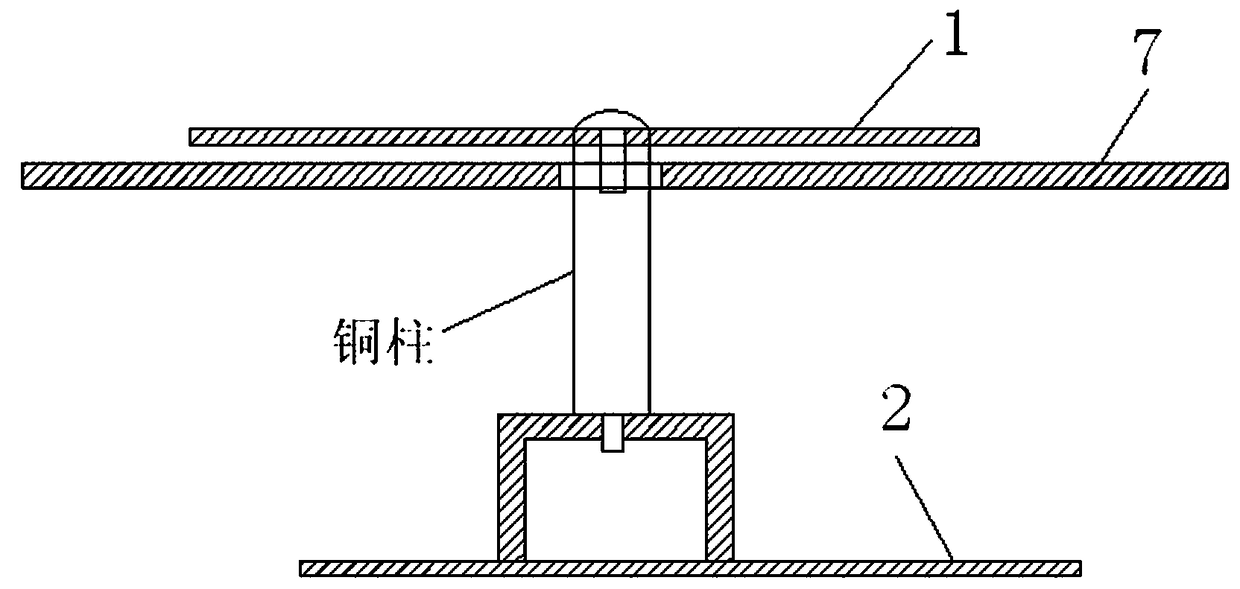
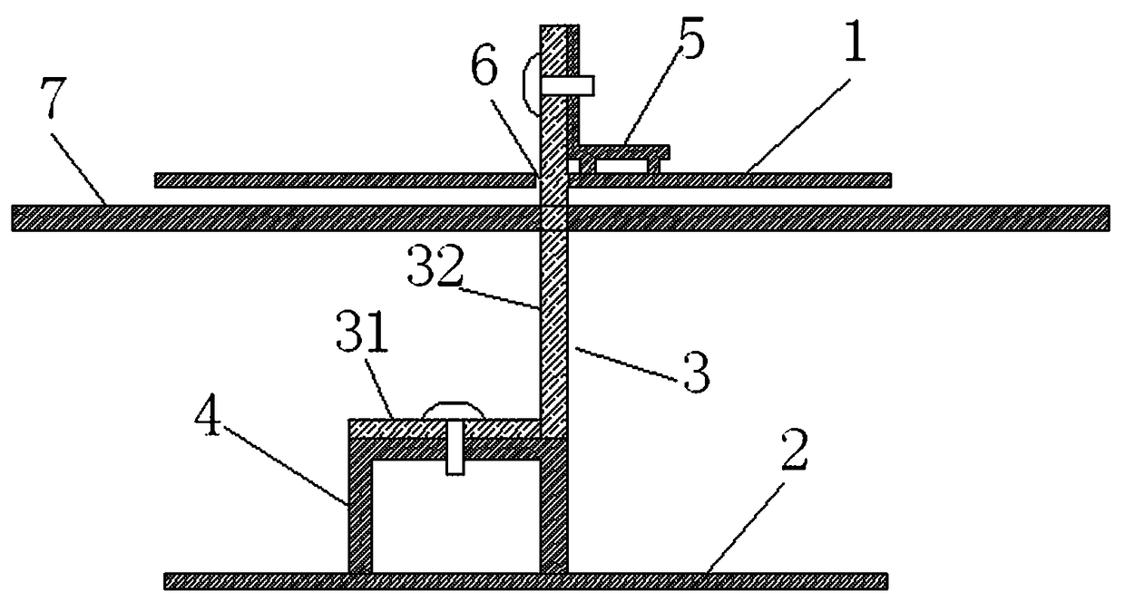
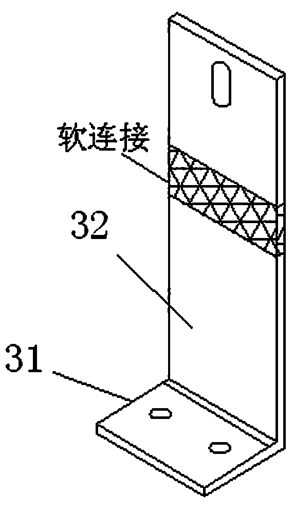
[0019] like figure 2 and image 3 Shown is a copper bar connection device for UPS circuit boards, including an upper PCB board 1, a lower PCB board 2 and a copper bar 3 connecting the upper PCB board and the lower PCB board, and the lower PCB board 2 is provided with The lower connecting terminal 4 of internal thread, the lower screw hole of the lower connecting terminal 4 is located directly above the connecting terminal, the upper connecting terminal 5 with internal thread is arranged on the upper PCB board 1, and the upper screw hole of the upper connecting terminal 5 is located at the wiring terminal. On the side of the terminal, the upper ...


PUM


Abstract

The present invention relates to a copper bar connection device between UPS circuit boards. The device comprises an upper PCB, a lower PCB and a copper bar connected with the upper PCB and the lower PCB, the lower PCB is provided with a lower connection terminal with internal threads, a lower screw hole of the lower connection terminal is located above a wiring terminal, the upper PCB is providedwith an upper connection terminal with internal threads, an upper screw hole of the upper connection terminal is located at the side of the wiring terminal, a slit capable of allowing the copper bar to pass through is arranged beside the wiring terminal on the upper PCB, a separator is arranged between the upper PCB and the lower PCB, and the separator is taken as a support piece of the upper PCB.The copper bar connection device simplifies design difficulty and requirements of the connection copper bar so as to save the processing cost of the connection copper bar, simplify the installation process, the installation is convenient, and the safety is improved.

Description

technical field [0001] The invention relates to a UPS power supply, in particular to a copper bar connection device for UPS circuit boards. Background technique [0002] At present, modular UPS products generally adopt a layered design method to solve problems such as heat dissipation and dust prevention. Place the devices and circuit boards with high heating power in the air duct layer (usually in the lower layer of the case), and place the devices with low heating power in the airtight layer (usually in the upper layer of the case). Such a design can meet the dual needs of heat dissipation and dust prevention. Since the circuit boards are in different layers of the chassis, a certain connection method is required to transmit electric energy between the circuit boards. Since the voltage and current of the electric energy transmitted between the internal circuit boards of the UPS are relatively large, it is necessary to use a method that can Electrical connection that with...

Claims


Application Information

Patent Timeline
Patent Type & Authority Applications(China)
IPC IPC(8): H01R4/38H01R12/50H01R12/55
CPCH01R4/38H01R12/50H01R12/55
Inventor 邹爱龙
Owner BAINADE CHINA YANGZHOU
Why Eureka
Try Eureka