
Electromagnetic-wave-shielding adhesive film, process for producing the same, and method of shielding adherend from electromagnetic wave

A technology for bonding films and conductive adhesives, applied in the direction of conductive adhesives, magnetic field/electric field shielding, adhesive types, etc., can solve the problem of insufficient repeated bending resistance, bending resistance and heat resistance sexual issues

Active Publication Date: 2010-01-20
TOYO INK SC HOLD CO LTD
View PDF6 Cites 2 Cited by
  • Summary
  • Abstract
  • Description
  • Claims
  • Application Information

AI Technical Summary

Problems solved by technology

However, conventional adhesive layers do not have sufficient bending resistance and sufficient heat resistance, and are not sufficiently resistant to repeated bending especially when used in flexible printed circuit board applications.

Method used

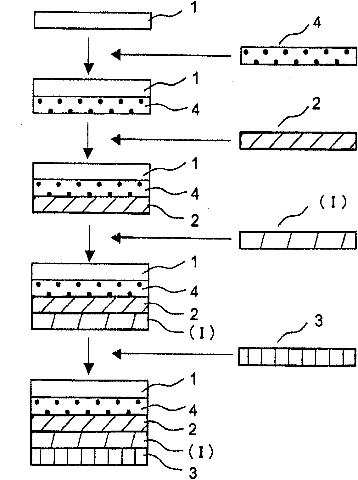
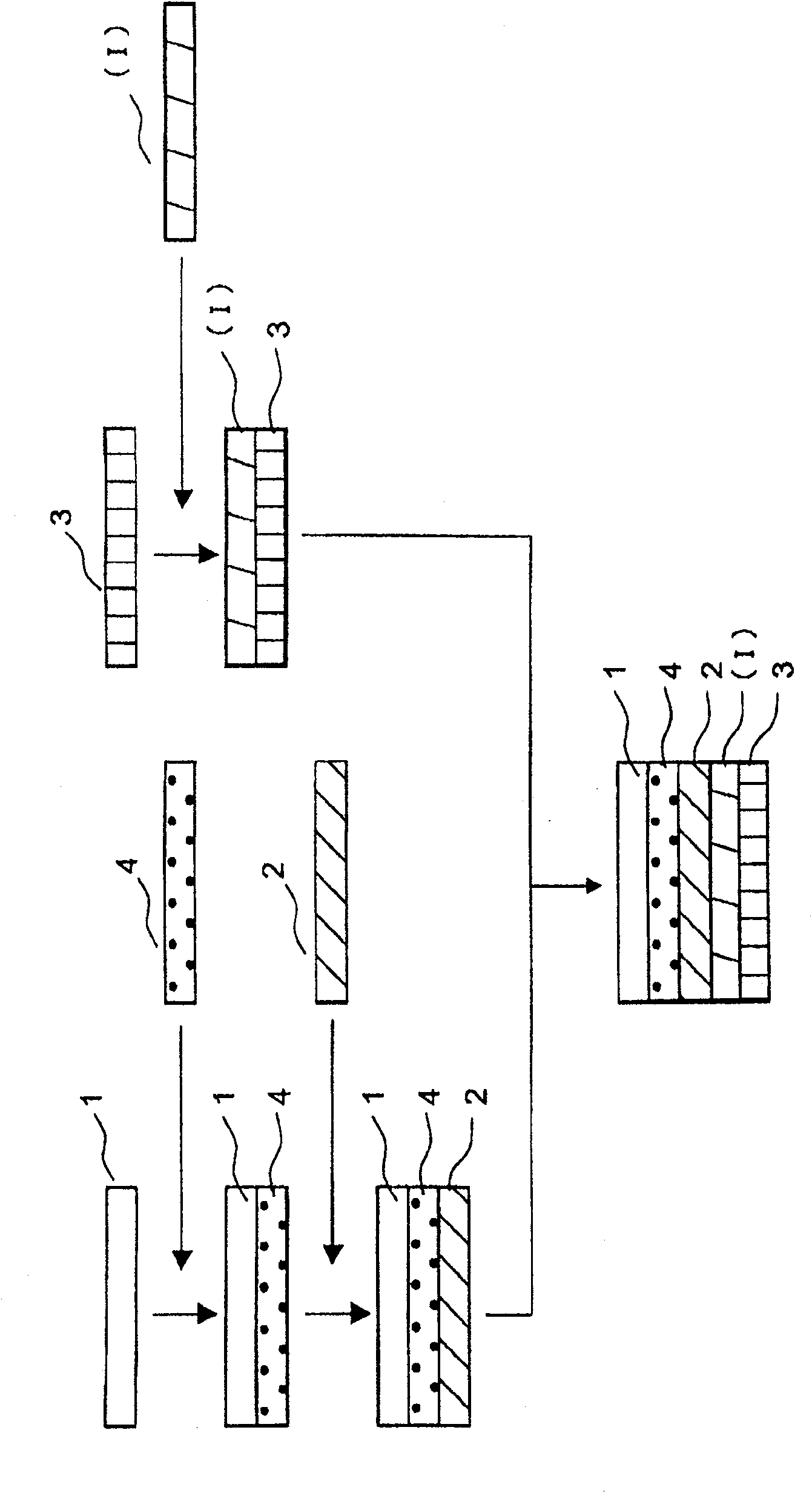

Image

  • Electromagnetic-wave-shielding adhesive film, process for producing the same, and method of shielding adherend from electromagnetic wave
  • Electromagnetic-wave-shielding adhesive film, process for producing the same, and method of shielding adherend from electromagnetic wave
  • Electromagnetic-wave-shielding adhesive film, process for producing the same, and method of shielding adherend from electromagnetic wave

Examples


Embodiment 1

[0235] With respect to 333 parts of polyurethane polyurea resin solutions (A-1), add 20 parts of bisphenol A type epoxy resins ("Epicoat 828" produced by Japan Epikisilesin, epoxy equivalent = 189g / eq), obtain bonding resin composition. 180 parts of flaky silver powder ("AgXF-301" manufactured by Fukuda Metal Foil Powder Co., Ltd.) was added to 353 parts of this adhesive resin composition, and stirred and mixed to obtain a curable conductive adhesive composition.

[0236] Next, a polyethylene terephthalate film ("SA-125PET" produced by Unichika) with a thickness of 125 μm was used as a reinforcing film, and a micro-adhesive with heat resistance was applied using a micro gravure coater. ("BPS5525" manufactured by Toyo Ink Manufacturing Co., Ltd.) was dried to a thickness of 2 µm (dry film thickness) to form a slight adhesive layer. A 9 μm-thick polyphenylene sulfide film (“Trelina 3030” manufactured by Toray) was laminated as a base film on the micro-adhesive layer to obtain a...

Embodiment 2

[0239] With respect to 333 parts of polyurethane polyurea resin solutions (A-2), add 10 parts of bisphenol A type epoxy resins ("Epicoat 828" produced by Japan Epikisilesin, epoxy equivalent = 189g / eq), 0.7 parts of micro Dicyandiamide ("Epiquiy DICY 7" manufactured by Japan Epoch Resin) and 0.1 part of imidazole-based curing accelerator ("PN-40" manufactured by Ajinomoto Fain Techno) were pulverized to obtain an adhesive resin composition. 166 parts of flaky silver powder ("AgXF-301" produced by Fukuda Metal Foil Powder Co., Ltd.) was added to 343.8 parts of this adhesive resin composition, and stirred and mixed to obtain a curable conductive adhesive composition.

[0240] Next, a polyethylene terephthalate film ("SA-125PET" produced by Unichika) with a thickness of 125 μm was used as a reinforcing film, and a micro-adhesive with heat resistance was applied using a micro gravure coater. ("BPS5525" manufactured by Toyo Ink Manufacturing Co., Ltd.) was dried to a thickness of 2...

Embodiment 3-11

[0243] Except using the polyurethane polyurea resin solution, epoxy resin and flaky silver powder of the type and amount shown in Table 1 and Table 2, repeat the operation of Example 1 to prepare various curable conductive adhesive compositions, prepare Electromagnetic shielding adhesive film.


PUM

PropertyMeasurementUnit
acid valueaaaaaaaaaa
glass transition temperatureaaaaaaaaaa
epoxy equivalentaaaaaaaaaa

Abstract

An electromagnetic-wave-shielding adhesive film which comprises a base film and a curable conductive adhesive layer (I), wherein the curable conductive adhesive layer (I) comprises: a polyurethane-polyurea resin (A) prepared by reacting a polyamino compound (e) with a urethane prepolymer (d) having an isocyanate group at an end and obtained by reacting a carboxylated diol compound (a), a polyol (b) which has a number-average molecular weight of 500-8,000 and is not a carboxylated diol compound, and an organic diisocyanate (c); an epoxy resin (B) having two or more epoxy groups; and a conductive filler.

Description

technical field [0001] The present invention relates to an electromagnetic wave shielding adhesive film, a preparation method thereof, and an electromagnetic wave shielding method of an adherend. The electromagnetic wave-shielding adhesive film of the present invention is bonded to a flexible printed wiring board subjected to repeated bending, and is suitable for use in shielding electromagnetic interference generated by electronic circuits. Background technique [0002] Flexible printed circuit boards are bendable, and respond to the further performance and miniaturization requirements of OA equipment, communication equipment, mobile phones, etc. in recent years, and are often used to assemble electronic circuits into narrow and complex structures. With the miniaturization and frequency increase of such electronic circuits, countermeasures against unnecessary electromagnetic noise generated thereby are becoming more and more important. Therefore, conventionally, an electro...

Claims


Application Information

Patent Timeline
Patent Type & Authority Patents(China)
IPC IPC(8): H05K9/00B32B27/00C08L63/00C08L75/04C09J9/02C09J163/00C09J175/04C09J7/35
CPCB32B2307/306C08G18/6541C09J9/02B32B7/12B32B27/08C09J7/0203C09J2463/00B32B2307/554H05K9/0088C08K3/08H01L2924/0002C08G18/0823B32B2457/08B32B27/20H01L23/552B32B2307/51B32B27/38C08G18/12B32B27/40C08G18/4045C09J2475/00C09J2463/006C09J7/35C08G18/3225H01L2924/00B32B27/00C08L75/04C08L63/00
Inventor 小林英宣西山祐司桑原章史松泽孝洋梅泽三雄坂井祥平
Owner TOYO INK SC HOLD CO LTD
Learn More