
Capillary pump cooler with micro-groove wing structure and its manufacturing method

A technology of cooling device and micro-groove, which is applied in the direction of cooling/ventilation/heating transformation, lighting and heating equipment, indirect heat exchanger, etc. Minimization and other issues, to achieve the effect of thin heat sink, no mechanical moving parts, and simple structure

Inactive Publication Date: 2009-06-03
SOUTH CHINA UNIV OF TECH
View PDF4 Cites 1 Cited by
  • Summary
  • Abstract
  • Description
  • Claims
  • Application Information

AI Technical Summary

Problems solved by technology

It is impossible to process multi-dimensional and multi-scale fin-structure functional surfaces with macrostructure, substructure and microstructure superimposition
The micro-groove processing of the microstructure can adopt micro-nano processing technology. At present, there are many technologies such as laser engraving, chemical corrosion, chemical vapor deposition, and reactive ion etching, but these technologies can only be processed to produce a specific scale. The structure within the range, and these processes are still in the research stage and have not yet been industrialized, and their processing costs are high and difficult

Method used


Image

  • Capillary pump cooler with micro-groove wing structure and its manufacturing method
  • Capillary pump cooler with micro-groove wing structure and its manufacturing method
  • Capillary pump cooler with micro-groove wing structure and its manufacturing method

Examples


Embodiment Construction

[0036] The present invention will be described in further detail below in conjunction with the embodiments and accompanying drawings, but the protection scope of the present invention is not limited to the range indicated by the embodiments.

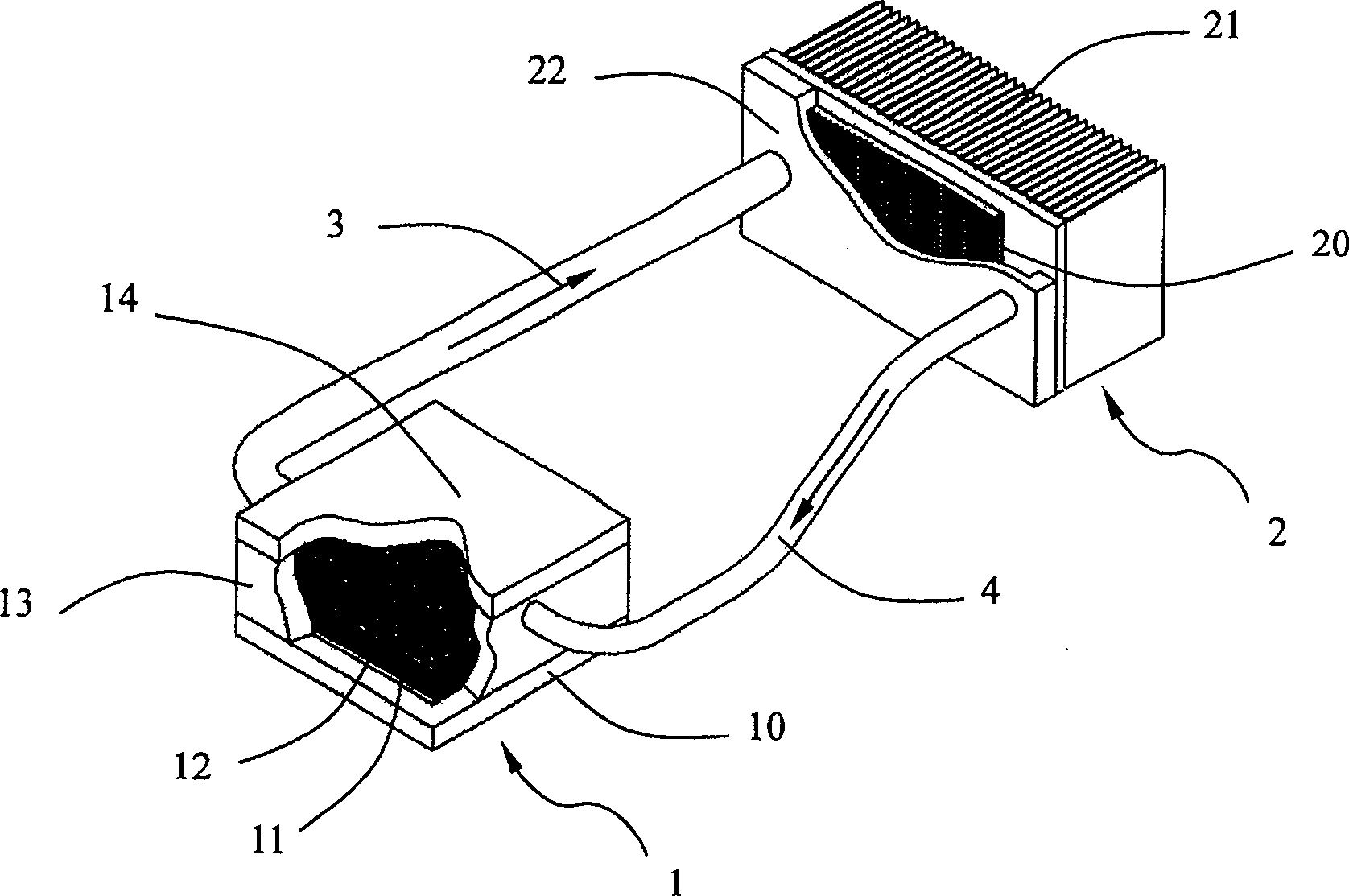
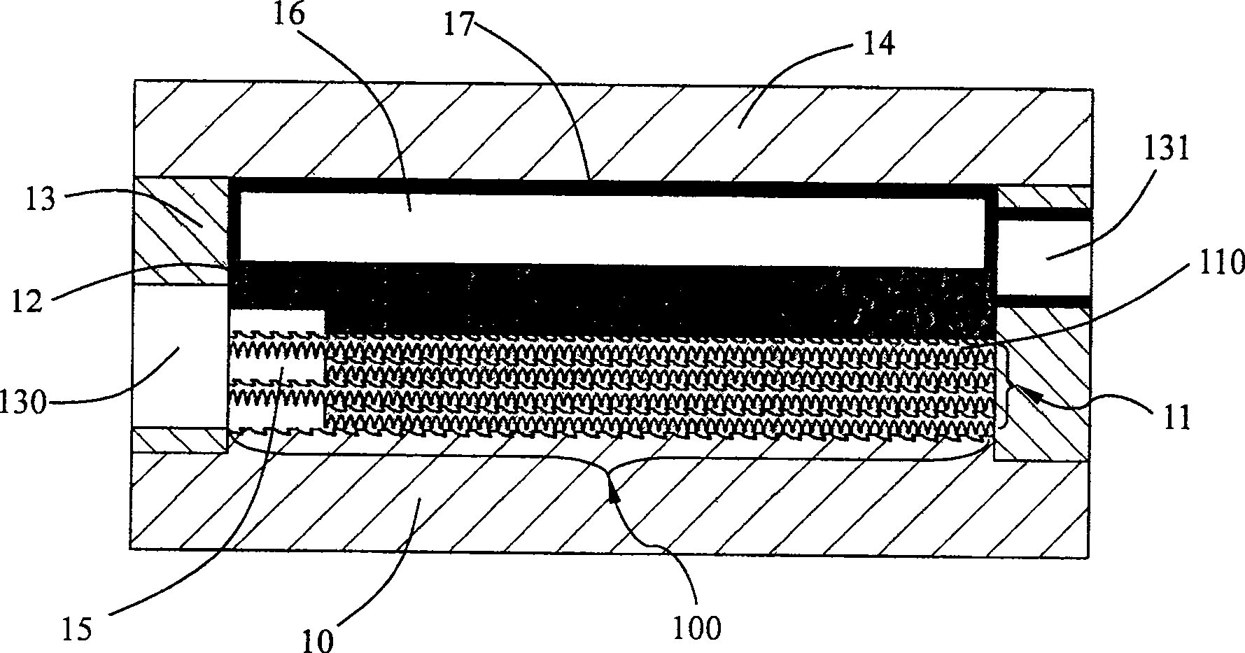
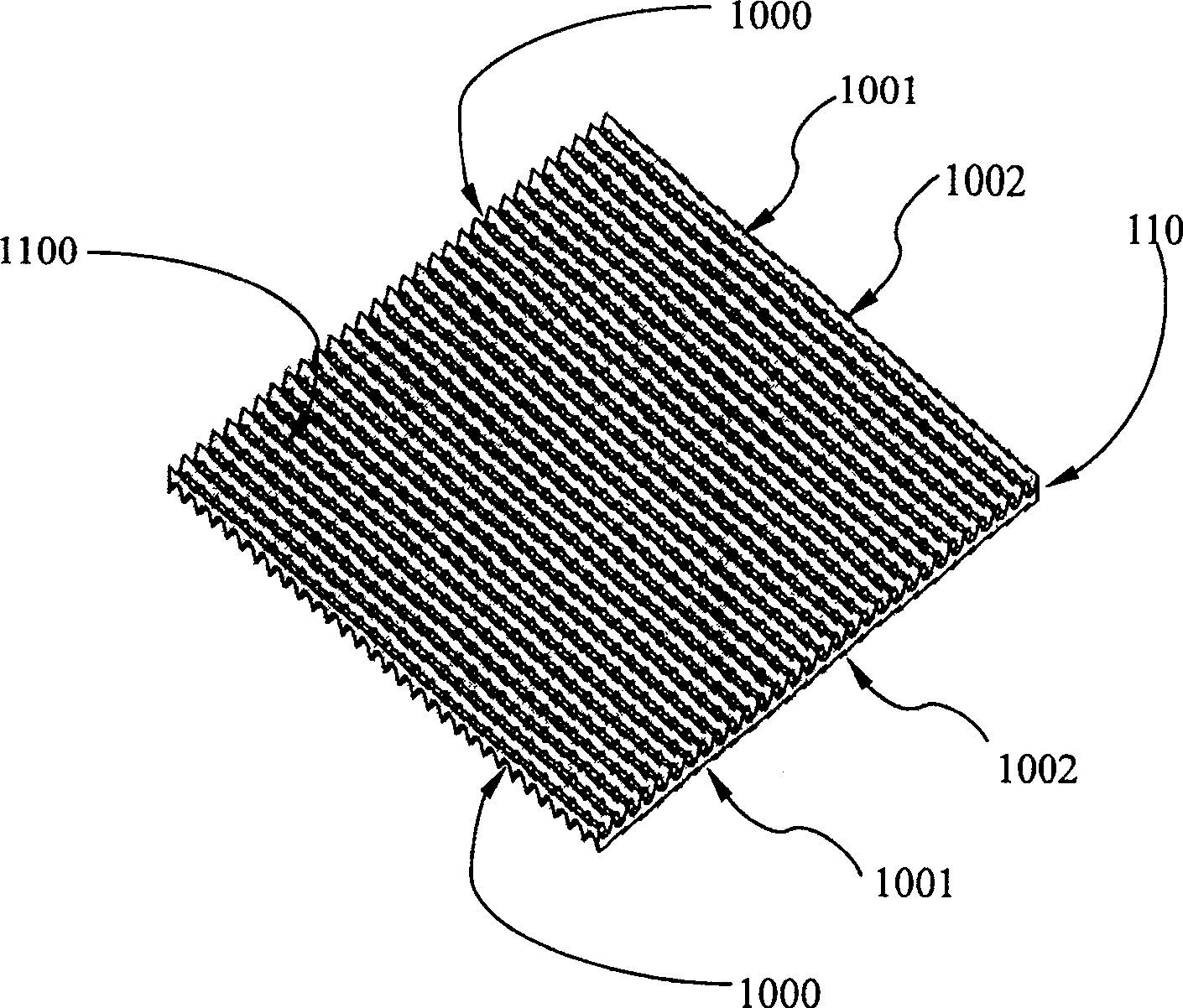
[0037] Such as figure 1 As shown, the capillary pump cooling device with a micro-groove fin structure includes an evaporator 1, a condenser 2, a steam manifold 3 and a liquid manifold 4, and the interior is filled with a certain amount of liquid working fluid whose boiling point is lower than the temperature to be radiated , In this embodiment, the working fluid is methanol, with a boiling point of 64.7°C. According to heat dissipation requirements, the liquid working fluid can also use ethanol, ethylene, acetone, ammonia water, isobutane, FC-72, PF-5060, HCFC 141b and other different working fluids. The evaporator 1 and the condenser 2 are connected by a steam connecting pipe 3 and a liquid connecting pipe 4 to form a loop system, and ...


PUM


Abstract

The invention relates to a capillary pumping cooling device with micro-groove wing structure, which comprises: an evaporator connected to a condensator by a steam union pipe and a liquid union pipe to form a system for operating means circulation; arranging a plurality of crossed-intercommunicating boiling strengthened plates with micro-groove wing structure on both sides. This invention is used mainly for heat dissipation of micro-electron chip. Wherein, this invention uses plough cutting-extrusion molding technology for micro-groove wing structure and planing forming technology for integrated wing cooling fin with low cost and high efficiency, which benefits to reinforce boiling, promote condensation and speed up convective dissipating heat.

Description

technical field [0001] The invention relates to a cooling technology, especially a cooling technology for electronic chips. Specifically, it adopts the principle of phase change for heat transfer, and is mainly used for heat dissipation of microelectronic chips to solve the problem of thermal diffusion of microelectronic chips under the condition of high heat flux density. A capillary pump cooling device with a micro-groove fin structure and a manufacturing method thereof. Background technique [0002] With the rapid development of microelectronics technology, electronic products tend to develop in the direction of high performance, portability and miniaturization. The improvement of main frequency and integration of microprocessor chips has led to the problem of high heat flux, which has become the primary problem restricting the development of high-integration chip technology. For chips with high heat flux density, if the generated heat cannot be exported in time, the hea...

Claims


Application Information

Patent Timeline
Patent Type & Authority Patents(China)
IPC IPC(8): H01L23/427G06F1/20H05K7/20
CPCF28D15/0266
Inventor 汤勇池勇刘小康陈平万珍平
Owner SOUTH CHINA UNIV OF TECH
Learn More