Bipolar electrostatic chuck
An electrostatic chuck, bipolar technology, which is applied in the direction of holding devices, circuits, and electrical components that apply electrostatic attraction, can solve the problems of difficulty in removing the sample and inability to exert sufficient adsorption force.
- Summary
- Abstract
- Description
- Claims
- Application Information
AI Technical Summary
Problems solved by technology
Method used
Image
Examples
Embodiment 1
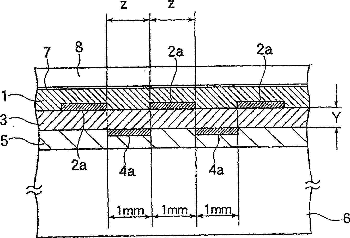
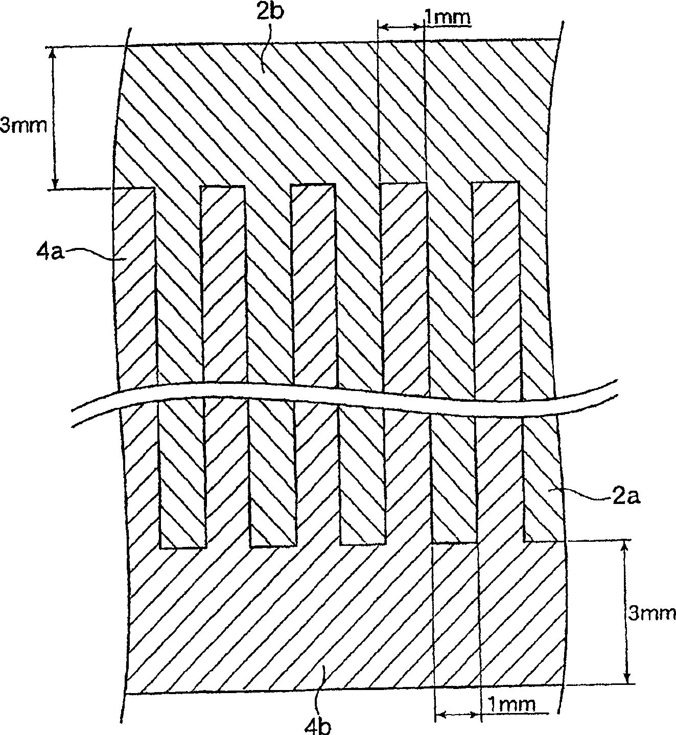
[0098] Fig. 1 shows the disassembled oblique view explanatory diagram of the bipolar electrostatic chuck of embodiment 1, this bipolar electrostatic chuck X comprises: length 100mm * width 100mm, film thickness 50μm and resistivity ε=3.5, has thermoplastic polymer on the lower surface An upper insulating layer 1 composed of a polyimide film of an imide film; a first electrode 2 composed of copper with a film thickness of 3 μm; a polyimide film with a length of 100 mm×width of 100 mm, a film thickness of 50 μm, and a resistivity ε=3.5 The inter-electrode insulating layer 3 composed; the second electrode 4 composed of copper with a film thickness of 3 μm; length 100 mm×width 100 mm, film thickness 50 μm and resistivity ε=3.5, polyimide with thermoplastic polyimide on the upper surface The lower insulating layer 5 is made of amine film; the metal substrate 6 is composed of aluminum with a length of 100 mm x a width of 100 mm x a thickness of 10 mm. In addition, in this bipolar el...
Embodiment 2
[0106] Figure 4 is a cross-sectional explanatory view of the bipolar electrostatic chuck X of Example 2, Figure 5 It is a partial plan explanatory view of the first electrode 1 and the second electrode 14 of the bipolar electrostatic chuck X of Example 2 viewed along the depth direction of the sample adsorption surface 7 .
[0107] In the bipolar electrostatic chuck X of Embodiment 2, the electrode width of the strip-shaped portion 14a of the second electrode 14 is formed at 0.6 mm, and the strip-shaped portion 14a of the second electrode 14 is located on the strip-shaped portion formed by the first electrode 2. In the center of the gap (1mm) formed by 2a, the strip-shaped comb teeth of the first electrode 2 and the strip-shaped comb teeth of the second electrode 14 are combined alternately, and the first electrode 2 and the second electrode 14 are combined along the depth direction of the sample adsorption surface 7. The two electrodes 14 are arranged so that the front end...
Embodiment 3
[0109] Fig. 6 is an exploded perspective explanatory view of the bipolar electrostatic chuck X of embodiment 3, Figure 7 It is an explanatory diagram of the cross section of the bipolar electrostatic chuck X of Example 3 (a part of the section A-A in FIG. 6 ), and FIG. A partial plan view of the adsorption surface 7 when viewed in the depth direction. The dotted area in FIG. 8 represents the portion where the second electrode 24 overlaps the first electrode 2 in the depth direction of the sample adsorption surface 7 .
[0110] The bipolar electrostatic chuck X of Example 3 was completed under the same conditions as in Example 1, except that the second electrode 24 was formed into a flat plate having a planar area of 80 mm in length and 80 mm in width.
PUM
 Abstract
Description
Claims
Application Information
 - R&D
- Intellectual Property
- Life Sciences
- Materials
- Tech Scout
- Unparalleled Data Quality
- Higher Quality Content
- 60% Fewer Hallucinations
Browse by: Latest US Patents, China's latest patents, Technical Efficacy Thesaurus, Application Domain, Technology Topic, Popular Technical Reports.
© 2025 PatSnap. All rights reserved.Legal|Privacy policy|Modern Slavery Act Transparency Statement|Sitemap|About US| Contact US: help@patsnap.com


