High efficiency low pollution hybrid Brayton cycle combustor

a combustor and high efficiency technology, applied in the direction of engines, machines/engines, mechanical equipment, etc., can solve the problems of limited general adoption, inability of such engines to meet sudden demand and/or maintain a constant working temperature or pressure, and inability to control such engines inefficiently, so as to achieve clean, efficient, pollution-free power

Inactive Publication Date: 2012-03-20
VAST POWER PORTFOLIO
View PDF96 Cites 14 Cited by
  • Summary
  • Abstract
  • Description
  • Claims
  • Application Information

AI Technical Summary

Benefits of technology

[0017]One of the objectives of this invention is to provide a new, thermodynamic power cycle, which can operate in an open or closed mod

Problems solved by technology

In these devices, temperature control is usually the result of feeding large quantities of excess compressed air.
Each of these prior engines has encountered difficulties which limit their general adoption as a power source for the operation of prime movers.
Among these difficulties have been the inability of such an engine to meet sudden demand and/or to maintain a constant working temperature or pressure as may be required for effi

Method used


Image

  • High efficiency low pollution hybrid Brayton cycle combustor
  • High efficiency low pollution hybrid Brayton cycle combustor
  • High efficiency low pollution hybrid Brayton cycle combustor

Examples


Embodiment Construction

A. Basic Configuration Of The Present System

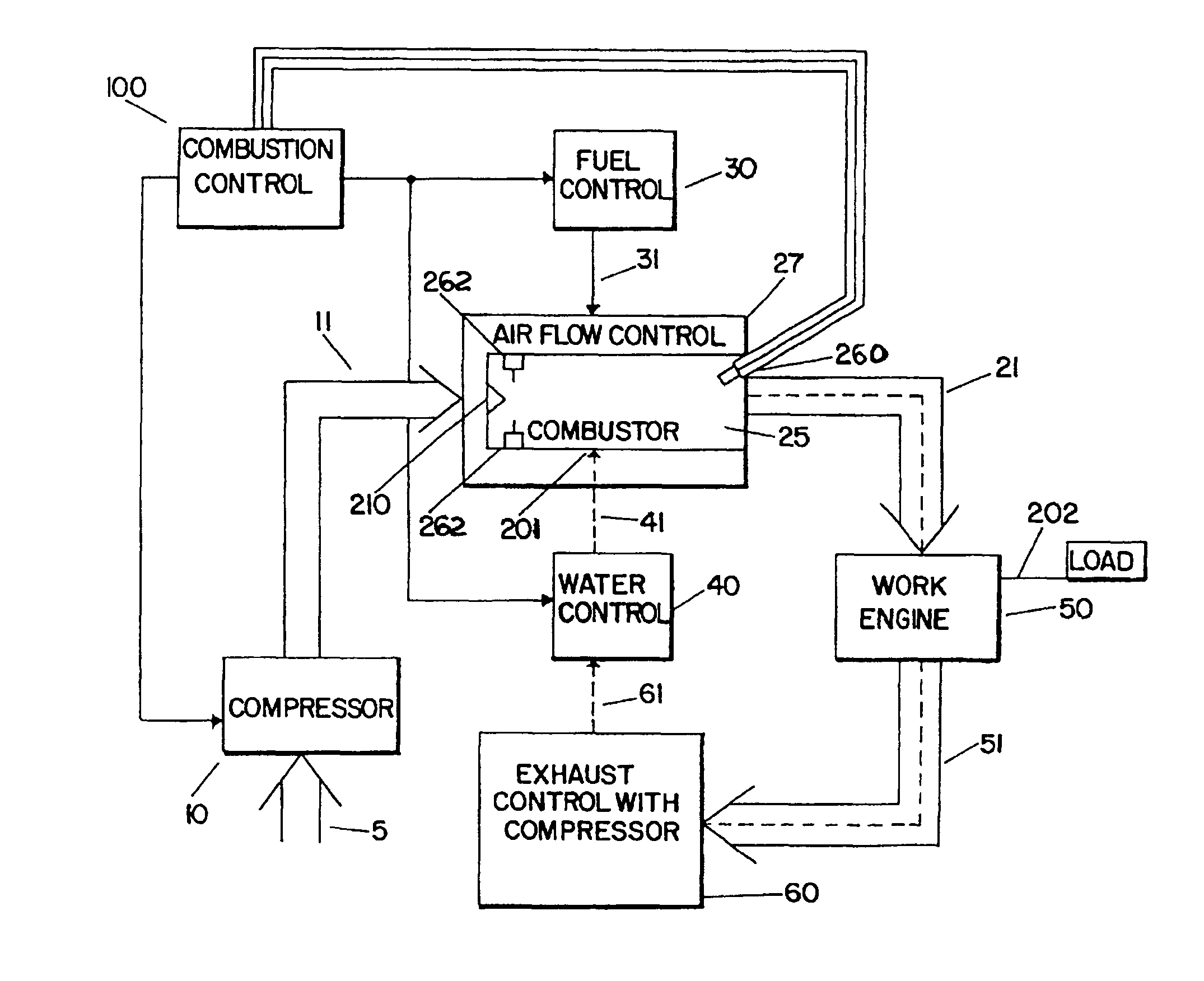
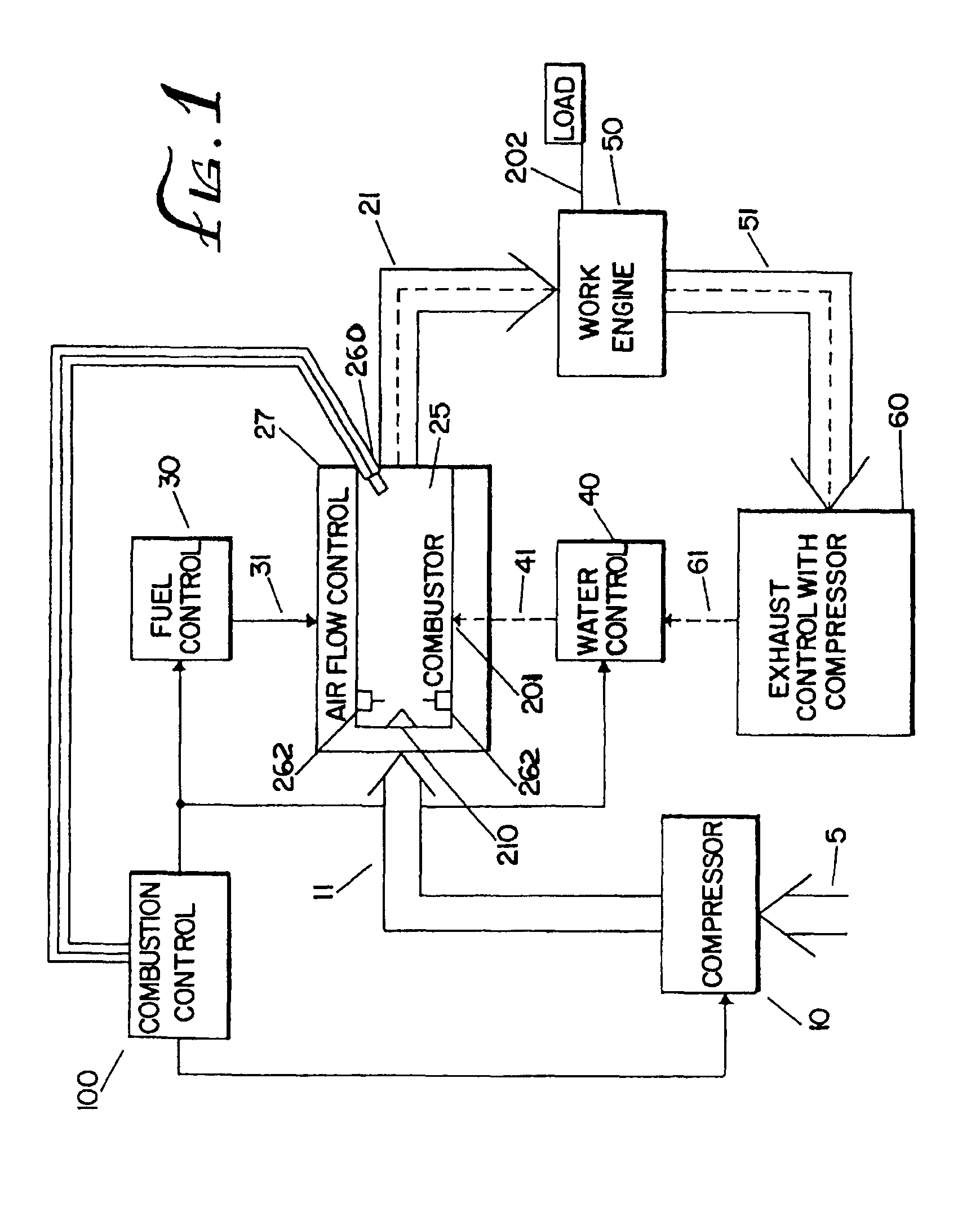
[0054]Referring now to FIG. 1, there is shown schematically a gas turbine engine embodying the teachings of the present invention. Ambient air 5 is compressed by compressor to a desired pressure resulting in compressed air 11. In a preferred embodiment, compressor 10 is a typical well-known two or three stage compressor, and the ambient air is compressed to a pressure greater than about four (4) atmospheres, and preferably 10 to 30 atmospheres. The temperature of the compressed air depends on the compression ratio. Al a compression ratio of 30:1 the compressed air temperature is approximately 1424° R (964° F.).

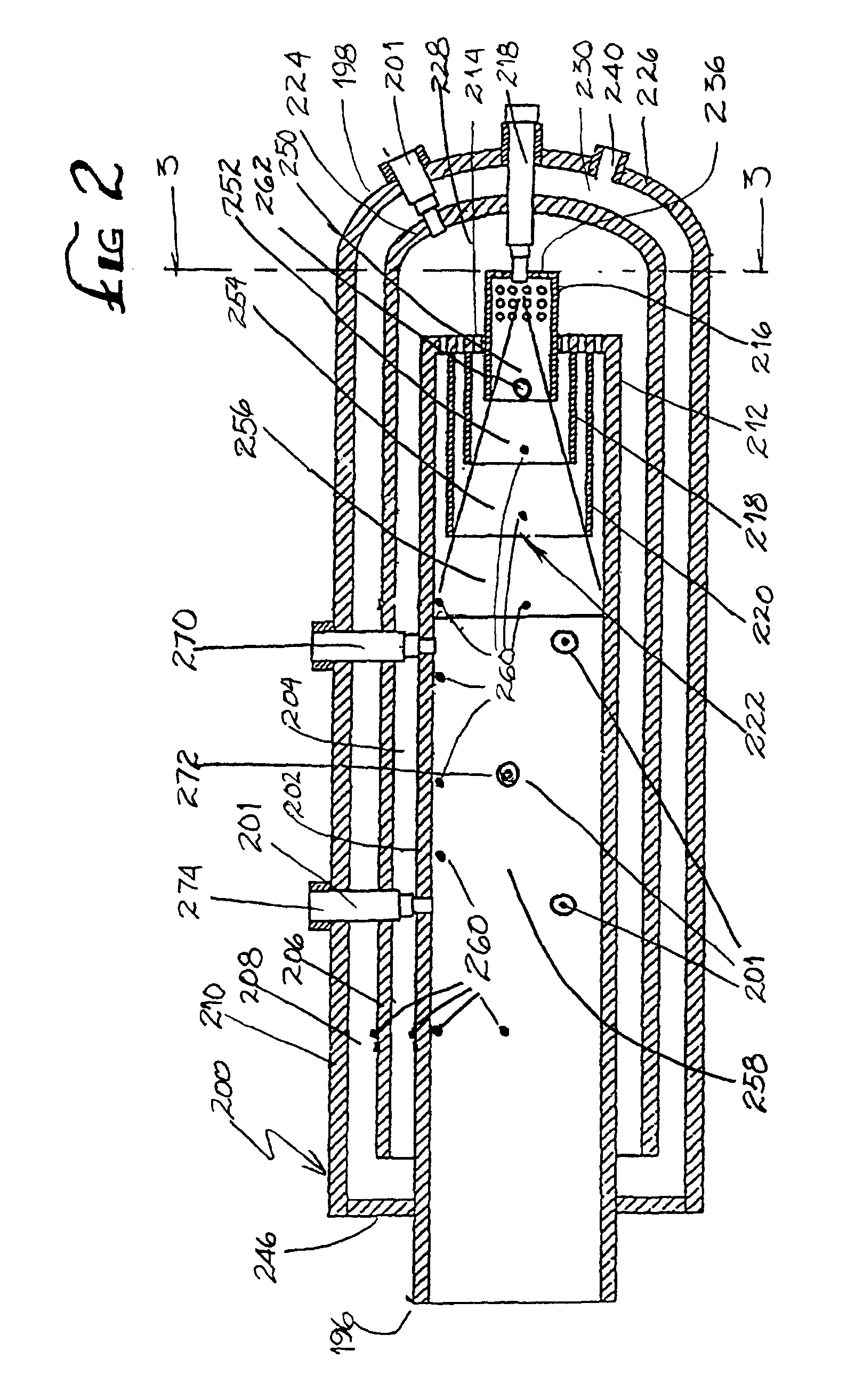
[0055]The flow of the compressed air 11 is controlled by an air flow controller 27 to a combustor 25. Combustors are well-known in the art. However, in the present invention, the compressed air 11 is supplied in a staged, circumferential manner by air flow control 27 to the combustor 200 shown in FIG. 2 and more fully described below...


PUM


Abstract

A power generating system is described which operates at high pressure and utilizes a working fluid consisting of a mixture of compressed non-flammable air components, fuel combustion products and steam. The working fluid exiting the power generating system is substantially free of NOx and CO.
Working fluid is provided at constant pressure and temperature. Combustion air is supplied by one or more stages of compression. Fuel is injected at pressure as needed. At least about 40% of the oxygen in the compressed air is consumed when the fuel is burned. Inert liquid is injected at high pressure to produce working an inert mass of high specific heat diluent vapor for use for internal cooling of the combustion chamber.
The use of non-flammable liquid injection inhibits the formation of pollutants, increases the efficiency and available horsepower from the system, and reduces specific fuel consumption. Control systems allow the independent control of the quantity, temperature and pressure of the air, fuel and non-flammable liquid introduced in the combustion chamber allowing control of the maximum temperature and average temperature within the combustion temperature as well as the temperature of the exhaust from the combustion chamber.

Description

[0001]This application is a continuation-in-part of U.S. application Ser. No. 08 / 232,047 filed Apr. 26, 1994 now U.S. Pat. No. 5,743,080 which is the U.S. National Stage of PCT / US93 / 10280 filed Oct. 27, 1993 and a continuation-in-patent of Ser. No. 07 / 967,289, U.S. Pat. No. 5,617,719 filed Oct. 27, 1992 all of which are incorporated by reference.FIELD OF THE INVENTION[0002]The present invention is directed to a vapor-air steam engine which operates at high pressure and utilizes a working fluid consisting of a mixture of fuel combustion products and steam with a minimal amount of excess compressed air. The invention is further directed to processes for producing electrical energy, usable shaft horsepower and / or large quantities of steam in a fuel burning system at high efficiency and low specific fuel consumption, while generating insignificant amounts of environmental pollutants (NOx, CO, particulates, unburned fuel). The invention is still further directed to the production of pota...

Claims


Application Information

Patent Timeline
IPC IPC(8): F02C3/30F02C9/48
CPCF01K21/047
Inventor GINTER, J. LYELLGINTER, LEGAL REPRESENTATIVE, GARY
Owner VAST POWER PORTFOLIO
Why Eureka
Try Eureka