
Laser apparatus enabling calculation of effective driving time and remaining lifetime taking account of drive conditions including temperature

a technology of effective driving time and remaining lifetime, applied in the field of laser apparatus, can solve the problems of delay in replacement of light source, inability to feed back to the reliability control of light source, short life, etc., and achieve accurate calculation, accurate estimation of remaining lifetime, and further reduction of reference data required for calculation of acceleration factor

Active Publication Date: 2018-02-06
FANUC LTD
View PDF7 Cites 0 Cited by
  • Summary
  • Abstract
  • Description
  • Claims
  • Application Information

AI Technical Summary

Benefits of technology

The laser apparatus described in this patent allows for quantitative evaluation of the lifetime or reliability of the light source, even if the drive conditions change, such as temperature. It can estimate the whole lifetime or remaining lifetime of the light source based on the performance index of the light source and its change rate. The apparatus can record the calculated lifetime, optical output, and other performance indicators, providing information for further improving calculation accuracy. This makes it easier to evaluate the performance and reliability of the light source and can help in improving the overall design of the laser apparatus.

Problems solved by technology

If the effective cumulative driving time is not known, for example, problems arise such as the characteristic of the light source degrading, and when the lifetime has exhausted, it is not known from the average light source whether degradation is fast or the lifetime is short, and it is not possible to feed back to the reliability control of the light source, and to judge the lifetime from the viewpoint of lifetime assurance.
In addition, if the accurate remaining lifetime is not known, problems occur such as preparation for replacement of the light source being delayed, and disorder arising in the production schedule for maintenance work.
In addition, although keeping the temperature condition of the light source almost constant is relatively easy in the case of the light source being water cooled, in the case of being air-cooled, which has merits in the point of portability or weight, size, etc., it is difficult to avoid the temperature condition of the light source from changing by the influence of the environmental temperature.
For this reason, the drive conditions such as optical output and driving current, or temperature condition of the light source are not necessarily constant, and it has been necessary to accurately calculate the effective driving time and effective cumulative driving time which is the cumulative value thereof, which are equivalent to the driving time and lifetime consumption of the light source driven at the standard drive conditions and standard temperature condition; however, with the conventional technology, for the light source of the laser apparatus for which the drive conditions including the temperature of the light source are not constant, it has not been possible to calculate an accurate effective driving time or effective cumulative driving time.
However, with the conventional technology, for the light source of a laser apparatus for which the drive conditions including the temperature of the light source are not constant, it may not be possible to calculate the originally accurate effective cumulative driving time, and for the light source driven at such conditions, it has not been possible to estimate the remaining lifetime if degradation has not manifested.
Furthermore, there is individual variation in the degradation rate of the characteristic of light sources, and moreover, degradation rate varies along with the elapse of effective cumulative driving time, and thus the matter of there being individual variation also in the way of change thereof makes accurate estimation of the remaining lifetime increasingly difficult.

Method used


Image

  • Laser apparatus enabling calculation of effective driving time and remaining lifetime taking account of drive conditions including temperature
  • Laser apparatus enabling calculation of effective driving time and remaining lifetime taking account of drive conditions including temperature
  • Laser apparatus enabling calculation of effective driving time and remaining lifetime taking account of drive conditions including temperature

Examples


first embodiment

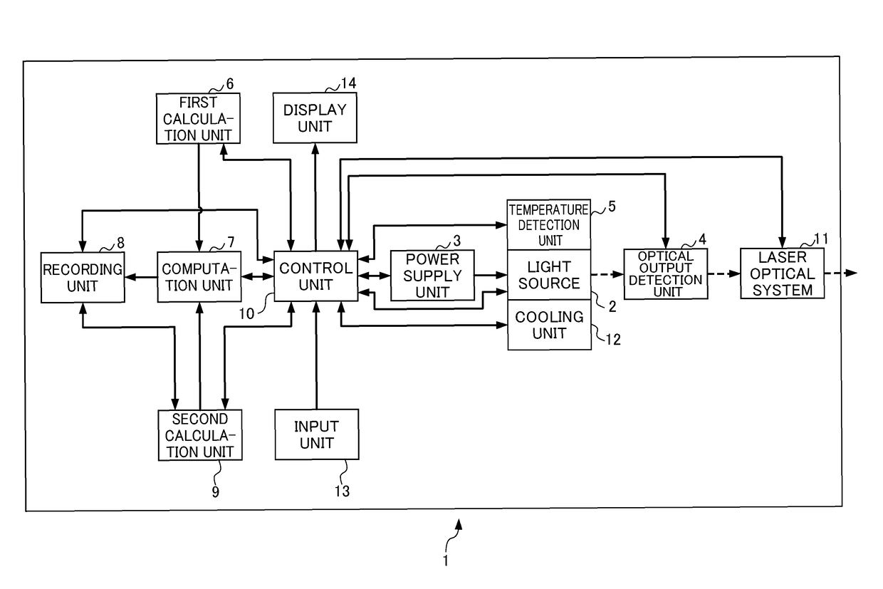
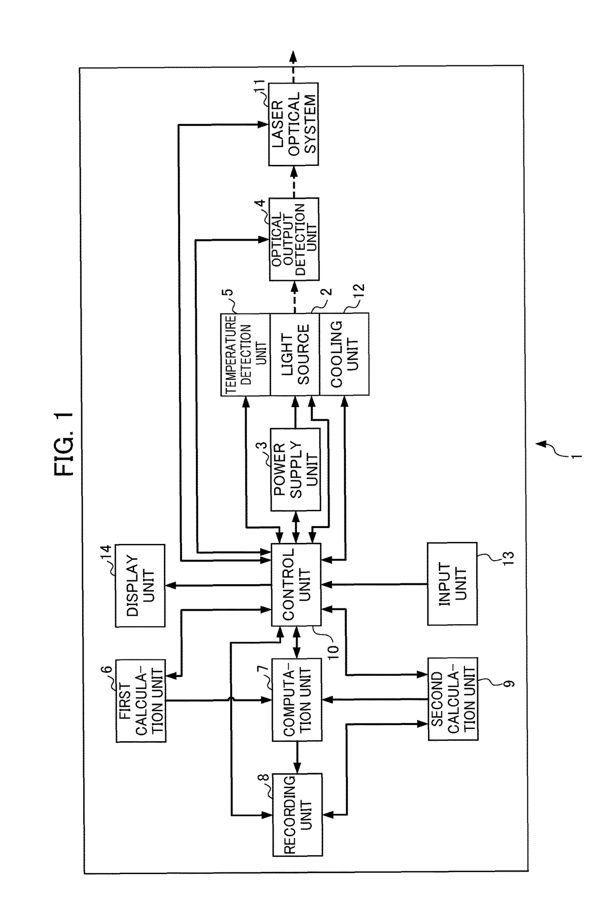
[0073]FIG. 1 is a schematic view showing the structure inside a laser apparatus 1 according to a first embodiment of the present invention. As shown in FIG. 1, the laser apparatus 1 according to the first embodiment includes: at least one light source 2 that functions as a laser source or excitation light source; at least one power supply unit 3 that supplies driving current to the light source 2; at least one optical output detection unit 4 that detects the optical output from the light source 2; at least one temperature detection unit 5 that detects the temperature of the light source 2 or a member thermally connected to the light source 2; a first calculation unit 6 that calculates an acceleration factor F (P,T) of lifetime consumption of the light source 2, which depends on the temperature T and drive condition value P, based on a case of a temperature TM detected by the temperature detection unit 5 or a temperature TL of the light source 2 obtained from a temperature TM detecte...

second embodiment

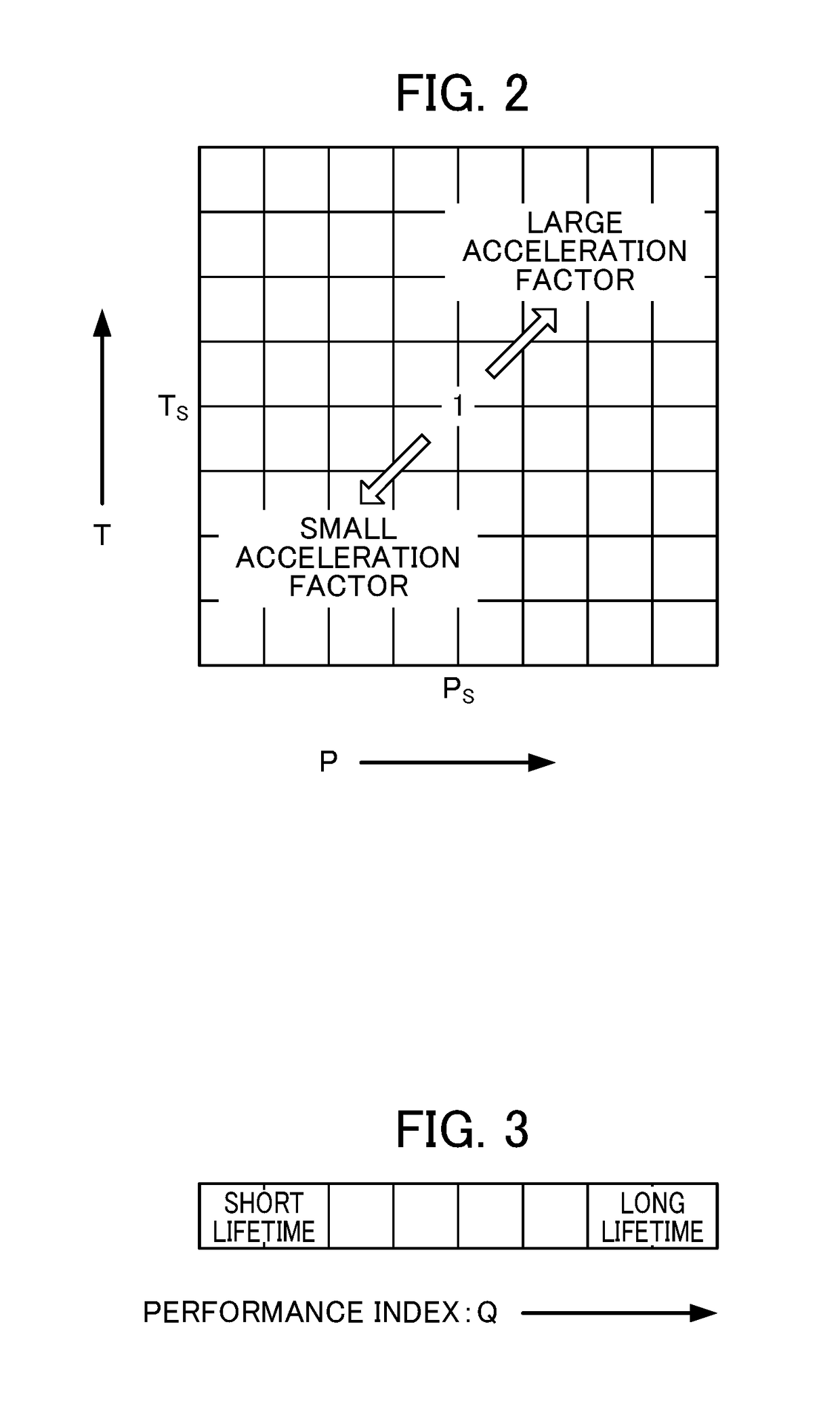
[0085]In a laser apparatus according to a second embodiment of the present invention, the dependence on the effective cumulative driving time tc is also considered in the acceleration factor F (P,T) calculated by the first calculation unit 6. FIG. 4 shows an organizational example of a data table referenced by the laser apparatus of a second example upon calculation of the acceleration factor F (P,T). A two-dimensional data table of one layer shown in FIG. 2 is included for each of a plurality of effective cumulative driving times. Upon referencing the data table of FIG. 4, in the case of there not being a data table in which effective cumulative driving time tc matches, it is possible to calculate the acceleration factor F (P,T) by interpolation, etc. When reaching the lifetime late stage, for the acceleration factor F (P,T) larger than the reference value being 1, even if the drive condition value P and temperature T are the same, there is a tendency for the acceleration factor F ...

third embodiment

[0086]In a laser apparatus according to a third embodiment of the present invention, the second calculation unit 9 can calculate the remaining lifetime τR of the light source 2 at an arbitrary time tp by subtracting the effective cumulative driving time tc until the arbitrary time tp recorded in the recording unit 8, from the whole lifetime τL of the light source 2 calculated relative to at least one characteristic of the light source 2 among the performance index Q of the light source 2 and the change rate of the performance index Q. In other words, it is possible to calculate as τR=τL−τc. The second calculation unit 9 can calculate the remaining lifetime τR by subtracting the effective cumulative driving time tc from the whole lifetime τL of the light source 2 calculated from the initial characteristic of the performance index Q, e.g., performance index Q at the setting time ts (i.e. effective cumulative driving time tc=0). Since the individual variations in light sources 2 such a...


PUM

PropertyMeasurementUnit
temperatureaaaaaaaaaa
temperature detectionaaaaaaaaaa
threshold currentaaaaaaaaaa

Abstract

A first calculation unit calculates an acceleration factor of lifetime consumption of the light source with as case of a standard temperature and standard drive condition as a reference, a second calculation unit calculates a whole lifetime or remaining lifetime of individual light sources relative to a performance index of the individual light sources or a change rate of the performance index, a computation unit obtains an effective cumulative driving time at which the magnitude of influence imparted on the lifetime is equivalent with a case of driving at the standard temperature and standard drive condition, by calculating a time integral of the acceleration factor, and a recording unit records the effective cumulative driving time and the whole lifetime or remaining lifetime together with an optical output characteristic of the light source.

Description

[0001]This application is based on and claims the benefit of priority from Japanese Patent Application No. 2016-136319, filed on 8 Jul. 2016, the content of which is incorporated herein by reference.BACKGROUND OF THE INVENTIONField of the Invention[0002]The present invention is a laser apparatus including a light source which is used as a laser light source or an excitation light source for laser oscillation, which is a laser apparatus that can accurately calculate an effective driving time for which the magnitude of the influence imparted on the lifetime of the light source is equivalent in a case of driving so that the temperature of the light source is the standard temperature and the optical output is a standard optical output, or a case of driving with the driving current of the light source at a standard driving current, even if the temperature of the light source changes, and even if the optical output from the light source or the magnitude of the driving current of the light...

Claims


Application Information

Patent Timeline
Patent Type & Authority Patents(United States)
IPC IPC(8): G01N21/00H01S5/00H01S5/062G01N21/68G01N21/64G01J3/02
CPCH01S5/0021H01S5/062G01N21/68G01N21/64G01J3/02H01S5/02423H01S5/0683H01S5/06837
Inventor TAKIGAWA, HIROSHIKAGIWADA, SATOSHI
Owner FANUC LTD
Learn More