
Epoxy resin compound and radiant heat circuit board using the same

a technology of epoxy resin and radiant heat circuit board, which is applied in the direction of printed circuit aspects, solid-state devices, and semiconductor/solid-state device details, etc., can solve the problems of difficult handling of epoxy resin, degrade the reliability of heat emitting devices, etc., and achieve high heat radiation properties, enhance crystalline properties, and increase thermal conductivity of radiant heat circuit board

Active Publication Date: 2016-05-31
LG INNOTEK CO LTD
View PDF18 Cites 0 Cited by
  • Summary
  • Abstract
  • Description
  • Claims
  • Application Information

AI Technical Summary

Benefits of technology

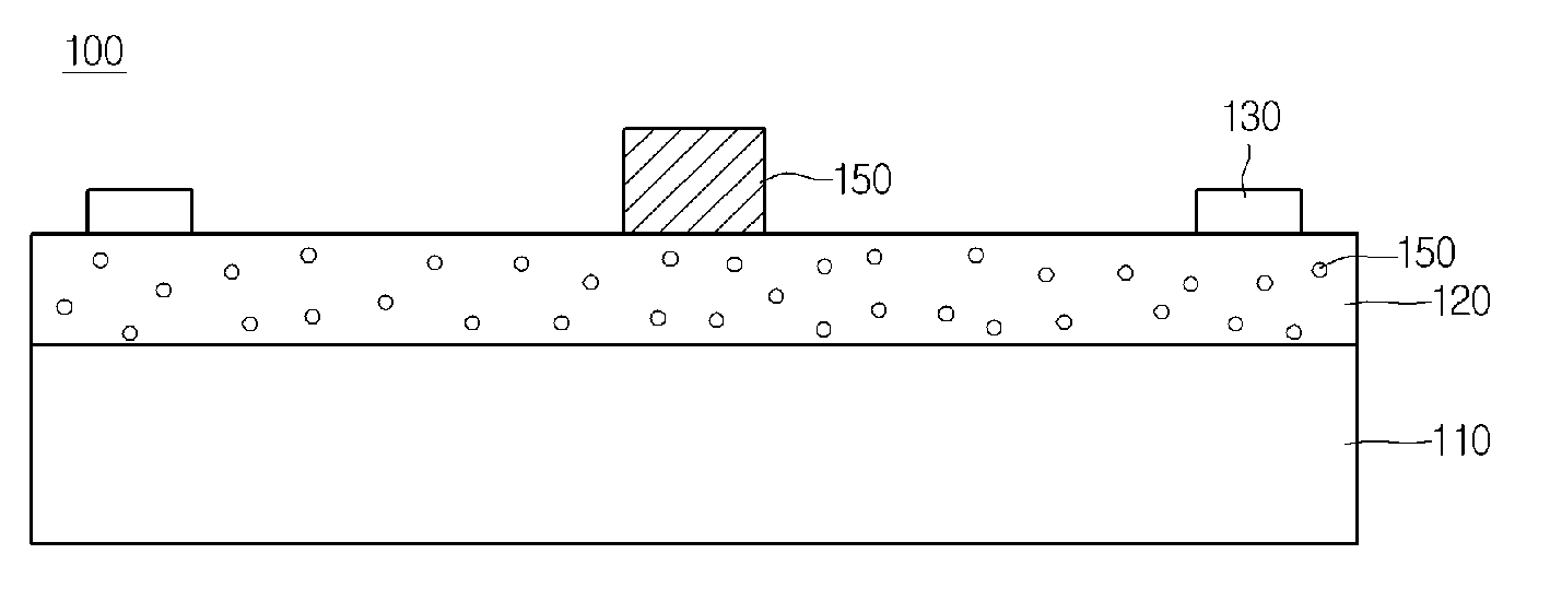
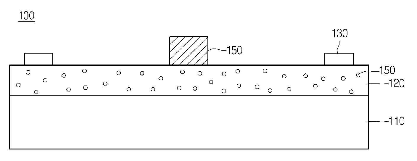
[0012]As described above, according to the embodiment, thermal conductivity of the radiant heat circuit board can be increased by using the epoxy resin including a mesogen structure to enhance a crystalline. In addition, the epoxy resin serving as an insulating material is used for the printed circuit board so that the substrate having a high heat radiation property can be provided. In addition, the epoxy adducts is formed the curing agent added to the crystalline epoxy resin, so that the solubility of the crystalline epoxy resin can be improved. And the amount used of curing agent decreases, so that the settlement can be improved.
[0013]The crystalline epoxy resin represents a superior molding property and a superior reliability, and represents high thermal conductivity, a low absorbable property, a low thermal expansion property, and a high heat resistance.

Problems solved by technology

The heat emitted from the heat emitting device increases the temperature of the circuit board to cause the erroneous operation of the heat light emitting device and to degrade the reliability of the heat emitting device.
Since the above epoxy resin is in a liquid phase at a room temperature, the handling of the above epoxy resin is difficult, and the above epoxy resin represents weak heat resistance, mechanical strength, and tensile force.

Method used


Image

  • Epoxy resin compound and radiant heat circuit board using the same
  • Epoxy resin compound and radiant heat circuit board using the same
  • Epoxy resin compound and radiant heat circuit board using the same

Examples


embodiment 1

[0069]3 w % of bisphenol-F, 3 w % of o-cresol-novolak, 2 w % of 4,4′oxybis(N-(4-(oxiran-2-ylmethoxy)benzylidene)aniline), 2% of NC-3000H epoxy resin (Nippon Kayaku co., Ltd), 2 w % of a DAS curing agent, 2 w % of a DAS curing accelerator, 0.5 wt % of BYK-W980, and 2.5 w % of epoxy adducts expressed in chemical formula 2 were mixed with each other and stirred at the temperature of 40 for 10 mins. Thereafter, 85 w % of an alumina inorganic filler was introduced into the mixture and stirred at the room temperature during 20 mins to 30 mins to obtain the crystalline epoxy resin compound of embodiment 1.

embodiment 2

[0070]3 w % of bisphenol-F, 2 w % of 4,4′oxybis(N-(4-(oxiran-2-ylmethoxy)benzylidene)aniline), 1.5 w % of NC-3000H epoxy resin (Nippon Kayaku co., Ltd), 1 w % of a DAS curing agent, 1.5 w % of epoxy adducts expressed in chemical formula 2, and 0.5 wt % of BYK-W980 were mixed with each other and stirred at the temperature of 40 for 10 mins. Thereafter, 88 w % of an alumina inorganic filler was introduced into the mixture and stirred at the room temperature during 20 mins to 30 mins to obtain the crystalline epoxy resin compound of embodiment 2.

embodiment 3

[0071]2 w % of bisphenol-F, 2 w % of o-cresol-novolak, 1 w % of 4,4′oxybis(N-(4-(oxiran-2-ylmethoxy)benzylidene)aniline), 2 w % of NC-3000H epoxy resin (Nippon Kayaku co., Ltd), 1 w % of a DAS curing agent, 1.5 w % of epoxy adducts expressed in chemical formula 2, 0.5 wt % of BYK-W980 were mixed with each other and stirred at the temperature of 40 for 10 mins. Thereafter, 90 w % of an alumina inorganic filler was introduced into the mixture and stirred at the room temperature during 20 mins to 30 mins to obtain the crystalline epoxy resin compound of embodiment 3.


PUM

PropertyMeasurementUnit
weightaaaaaaaaaa
thermal conductivityaaaaaaaaaa
electric insulatingaaaaaaaaaa

Abstract

Disclosed are an epoxy resin compound and a radiant heat circuit board using the same. The epoxy resin compound mainly includes an epoxy resin, a curing agent, and an inorganic filler. The curing agent comprises epoxy adducts formed to add the curing agent to a crystalline epoxy resin. The epoxy resin is used on a printed circuit board as an insulating material, so that a substrate having a high heat radiation property is provided.

Description

CROSS-REFERENCE TO RELATED APPLICATIONS[0001]This application is the U.S. national stage application of International Patent Application No. PCT / KR2012 / 006041, filed Jul. 27, 2012, which claims priority to Korean Application No. 10-2011-0075462, filed Jul. 28, 2011, the disclosures of each of which are incorporated herein by reference in their entirety.TECHNICAL FIELD[0002]The disclosure relates to an epoxy resin compound. In more particular, the disclosure relates to an epoxy resin compound used as an insulating layer of a radiant heat circuit board.BACKGROUND ART[0003]A circuit board includes a circuit pattern mounted on an electric insulating substrate, and is used to mount electronic parts thereon.[0004]The electronic parts may include a heat emitting device, for example, a light emitting diode (LED), and the heat emitting device significantly emits heat. The heat emitted from the heat emitting device increases the temperature of the circuit board to cause the erroneous operatio...

Claims


Application Information

Patent Timeline
Patent Type & Authority Patents(United States)
IPC IPC(8): C08G59/18C08G59/50H01L23/373H05K1/05H01L23/14C08L63/00H05K1/02C08G59/20H05K1/03
CPCH05K1/0201C08G59/184C08L63/00H01L23/142H01L23/3737H05K1/0373H05K1/056H01L2924/0002H05K2201/0209C08K2003/2227H01L2924/00C08K3/22C08K3/00C08G59/18H05K7/20
Inventor MOON, SUNG BAEPARK, JAE MANYOON, JONG HEUMKIM, HAE YEONCHO, IN HEE
Owner LG INNOTEK CO LTD
Learn More