
Partitioned hybrid substrate for radio frequency applications

a hybrid substrate and radio frequency technology, applied in the field of radio frequency signal system, can solve the problem of not providing a packaging system for radio frequency signals, and achieve the effect of reducing manufacturing costs and improving signal integrity

Inactive Publication Date: 2015-06-23
HONG KONG APPLIED SCI & TECH RES INST
View PDF9 Cites 3 Cited by
  • Summary
  • Abstract
  • Description
  • Claims
  • Application Information

AI Technical Summary

Benefits of technology

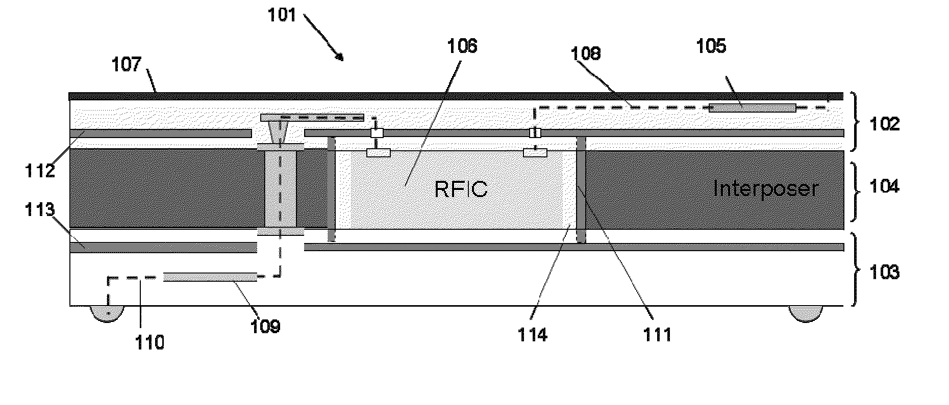
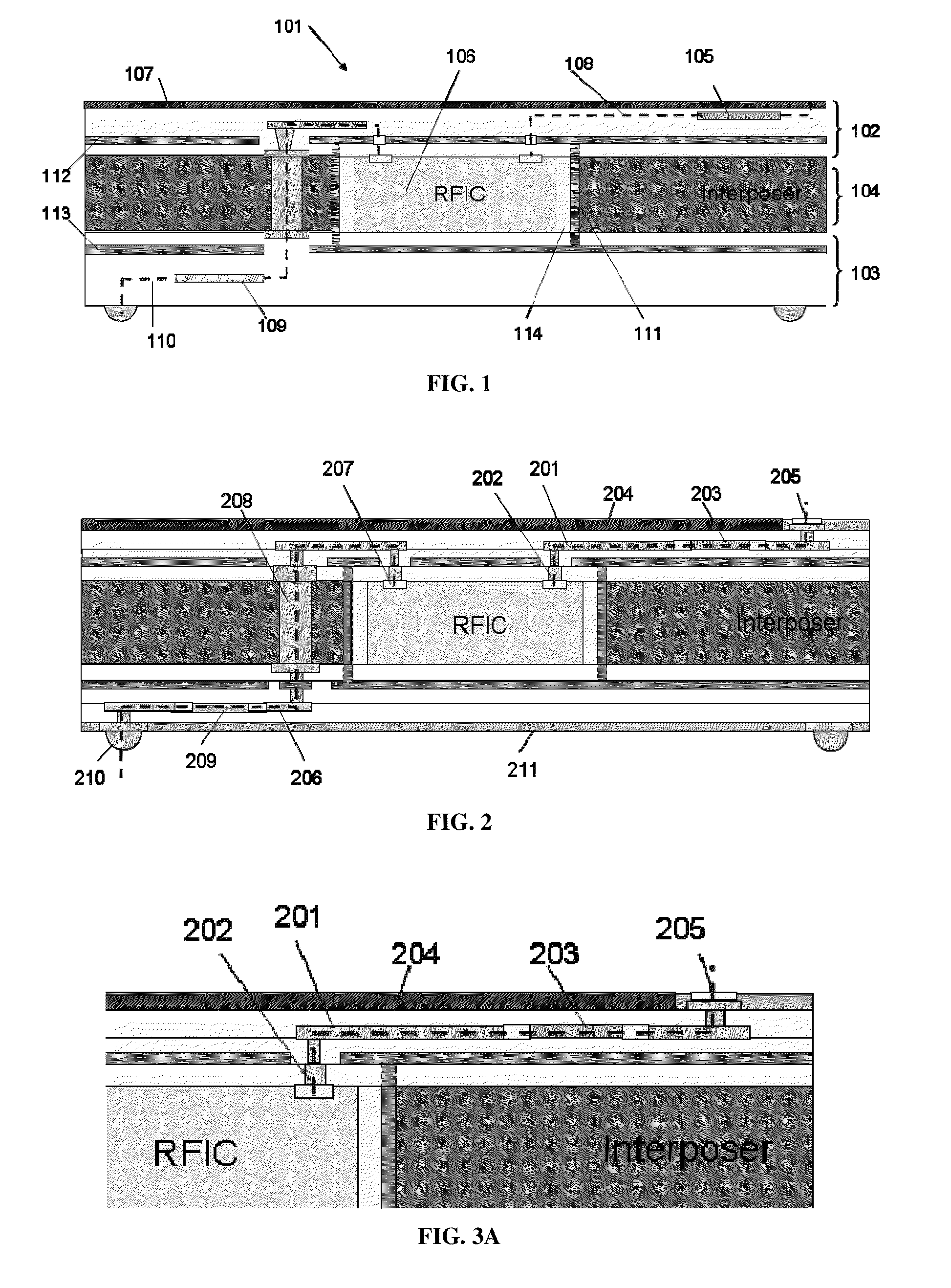
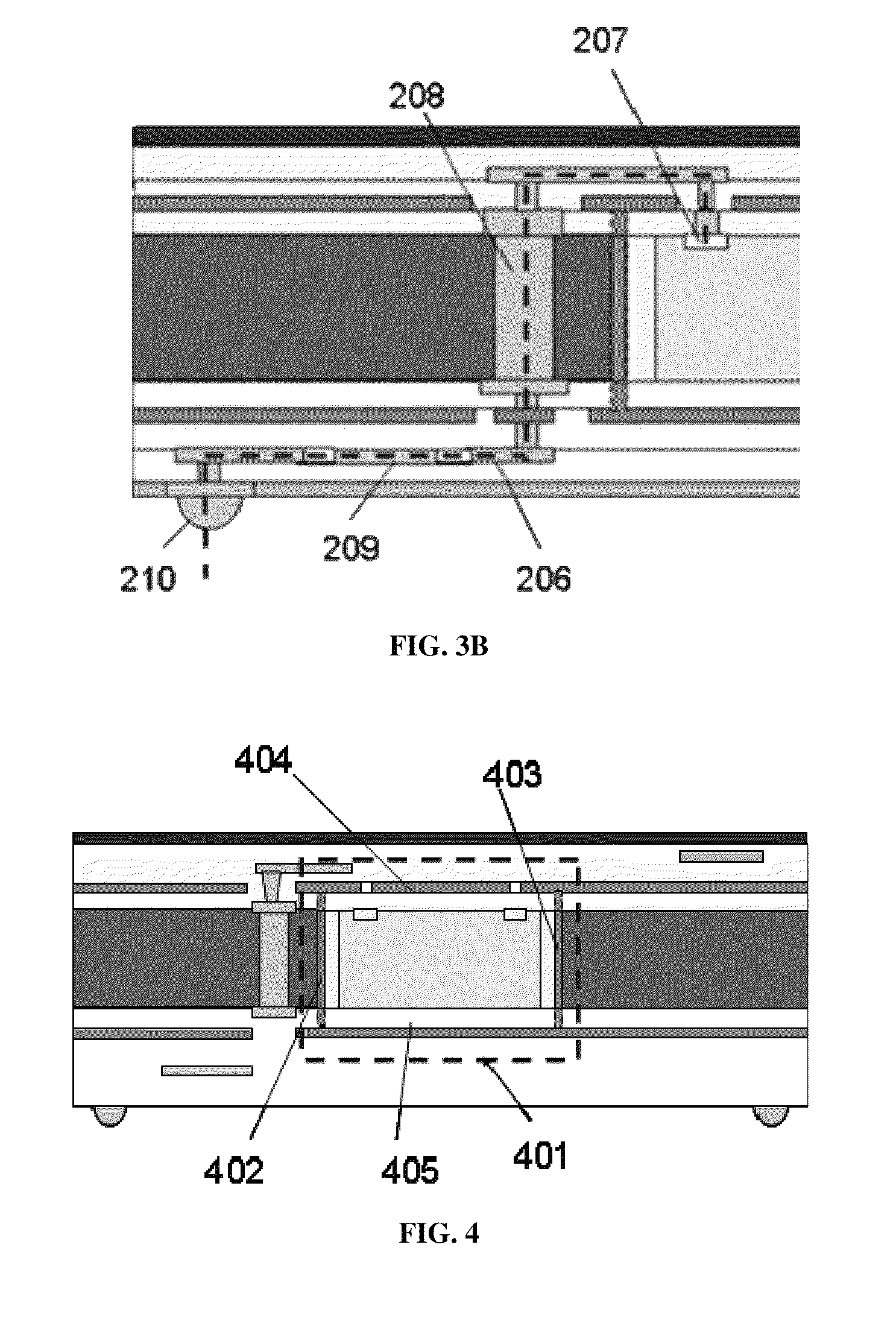
This patent is about a package for a compact radio frequency signal system that is designed to be small, have good signal quality, and be cost-effective to manufacture. The package is made up of a hybrid substrate with two layers that have different electrical properties. The top layer has a low loss dielectric material that is used to transmit RF signals to an antenna, while the bottom layer has a high loss dielectric material that is used to transmit low-frequency signals. The substrate also has an interposer that improves electrical isolation and mechanical stiffness. The interposer has an opening where the RFIC chip or other active components can be located. Metal layers are formed on the sidewalls of the opening to create a self-shielding enclosure that protects the RFIC chip from electromagnetic interference. The invention allows for a smaller, more efficient, and cost-effective package for RF signal systems.

Problems solved by technology

On the other hand, another critical issue is that radio frequency integrated circuit, being a sensitive device, should be electromagnetically shielded, while its antenna still keeps unaffected.
Nonetheless, the above prior arts fail to provide a packaging system for radio frequency signals, which carries optimized performance in electrical properties and EM shielding, an ultra-small form factor, and a low cost solution at the same time.

Method used


Image

  • Partitioned hybrid substrate for radio frequency applications
  • Partitioned hybrid substrate for radio frequency applications
  • Partitioned hybrid substrate for radio frequency applications

Examples


Embodiment Construction

[0027]In the following description, a package for radio frequency signal system is set forth as preferred examples. It will be apparent to those skilled in the art that modifications, including additions and / or substitutions may be made without departing from the scope and spirit of the invention. Specific details may be omitted so as not to obscure the invention; however, the disclosure is written to enable one skilled in the art to practice the teachings herein without undue experimentation.

[0028]FIG. 1 shows a package for radio frequency (RF) signal system according to one embodiment of the presently claimed invention. A package 101 includes a hybrid substrate having a sandwiched structure comprising an upper layer 102 and a lower layer 103 with different dielectric properties. The upper layer 102 and lower layer 103 are separated by an interposer 104 for improving electrical isolation and mechanical stiffness of the package 101. The interposer 104 has an opening, where a radio f...


PUM

PropertyMeasurementUnit
dielectricaaaaaaaaaa
relative permittivityaaaaaaaaaa
radio frequencyaaaaaaaaaa

Abstract

The presently claimed invention is to provide a package for compact RF signal system, and a method to form the package thereof in order to miniaturize the size of package, improve signal integrity, and reduce manufacturing cost. The package comprises a hybrid substrate with a sandwiched structure, in which the hybrid substrate comprises an upper layer and a lower layer with different dielectric properties being separated by an interposer for improving electrical isolation and mechanical stiffness. Metal layers are formed on the sidewalls of the opening to surround an active component, such that the metal sidewalls together with two ground plates in the upper and lower layers constitute a self-shielding enclosure inside the package to protect the active component.

Description

COPYRIGHT NOTICE[0001]A portion of the disclosure of this patent document contains material, which is subject to copyright protection. The copyright owner has no objection to the facsimile reproduction by anyone of the patent document or the patent disclosure, as it appears in the Patent and Trademark Office patent file or records, but otherwise reserves all copyright rights whatsoever.FIELD OF THE INVENTION[0002]The present invention relates generally to radio frequency signal system, and more specifically, to a package for compact radio frequency signal system, and a method for producing the package.BACKGROUND[0003]Currently, radio frequency or mixed signal system in portable / wearable electronics is urgently calling for heterogeneous integration (for example, integration of radio frequency, digital, and power systems) and reduced form factor so as to meet the need in miniaturizing the size of products. Advanced packaging technology such as three-dimensional packaging is a potentia...

Claims


Application Information

Patent Timeline
Patent Type & Authority Patents(United States)
IPC IPC(8): H05K1/18H05K1/02H05K3/00C23C28/00
CPCH05K1/024H05K3/0058H05K3/007C23C28/40Y10T156/1057H05K1/0224H05K1/0231H05K1/165H05K1/185H05K3/0097H05K3/429H05K3/4602H05K3/4688H05K2201/0187H05K2201/068H05K2201/0723H05K2201/09136H05K2201/09536H05K2201/09981H05K2201/10015H05K2201/1003H05K2201/1006H05K2201/10098H01L21/568H01L24/19H01L24/97H01L2224/04105H01L2224/73267H01L2924/15311H01L2924/3025H01L2223/6677
Inventor YANG, DANHE, SONGREN, YUXINGSHI, XUNQING
Owner HONG KONG APPLIED SCI & TECH RES INST
Learn More